Chapter 5 Instruction Specifications
5-81
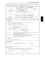
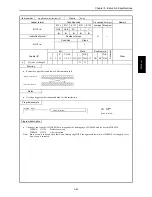
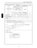
Item number
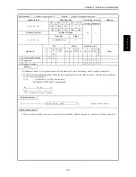
Application instructions-11
Name
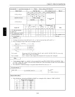
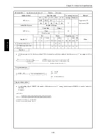
BCD shift left
Ladder format
Condition code
Processing time (
µ
s)
Remark
R7F4
R7F3
R7F2
R7F1
R7F0
Average Maximum
BSL (d, n)
DER
ERR
SD
V
C
Upper case: W
z
z
z
z
z
32
Lower case: DW
Instruction format
Number of steps
Condition
Steps
BSL (d, n)
3
39
Bit
Word
Double word
Usable I/O
X
Y
R,
M
TD, SS,
CU, CT
WX WY
WR,
WM TC DX DY
DR,
DM
C
o
nstant
Other
d
I/O to be shifted
{
{
{
{
{
n
Number of digits to be
shifted
{
{
{
{
{
The constant is set in
decimal.
Function
•
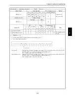
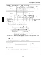
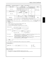
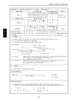
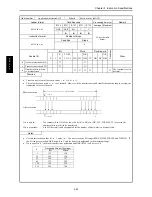
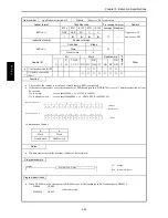
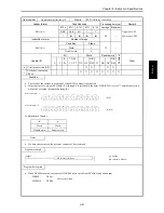
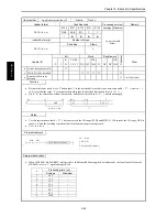
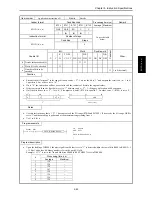
Shifts the contents of d to the left (toward the upper digits) by n digits (one digit is equivalent to 4 bits).
•
“0” is set from the least significant bit to the nth digit.
•
The digits from the most significant bit to the nth digit are discarded.
0
0000
d
0000
n digits
Most significant bit (MSB)
Least significant bit (LSB)
Discarded
Before execution
After execution
n digits
If d is a word:
Designates the shift amount, depending on the contents (0 to 3) of the lower 2 bits (b1, b0) of n (WX,
WY, WR, WM, TC). (Upper bits are ignored and considered as “0.”)
The n (constant) can be set to 0 to 3 (decimal).
If d is a double word:
Designates the shift amount, depending on the contents (0 to 7) of the lower 3 bits (b2 to b0) of n
(WX, WY, WR, WM, TC). (Upper bits are ignored and considered as “0.”)
The n (constant) can be set to 0 to 7 (decimal).
Notes
•
If n is equal to “0,” the shifting is not performed.
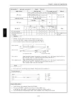
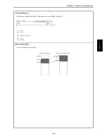
Program example
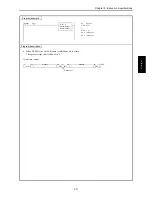
X00001
DIF1
BSL
(WR0000 ,1 )
LD
X00001
AND DIF1
[
BSL
(WR0000 ,1)
]
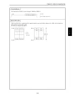
Program description
•
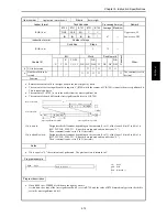
When X00001 rises, the content of WR0000 is regarded as BCD code and shifted to the left by four bits.
At this time, the data of the lower four bits are deleted and “0000” is set in the upper four bits.
H 1 2 3 4
H 2 3 4 0
0010 0011 0100 0000
0001 0010 0011 0100
Deleted
Before the shift
After the shift
Set to “0”
B
S
L (d
, n)
Summary of Contents for HIDIC MICRO-EH
Page 1: ...HITACHI PROGRAMMABLE CONTROLLER APPLICATION MANUAL NJI 350B X ...
Page 12: ...MEMO ...
Page 14: ...Chapter 1 Features 1 2 MEMO ...
Page 50: ...Chapter 4 Product lineup and wiring 4 18 MEMO ...
Page 196: ...Chapter 5 Instruction Specifications 5 146 ...
Page 263: ...Chapter 11 Communication Specifications 11 10 MEMO ...

