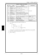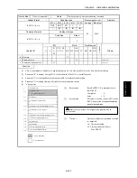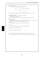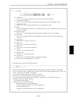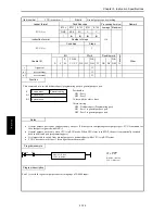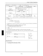
Chapter 5 Instruction specifications
5-119
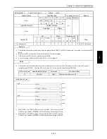
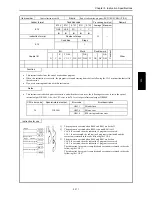
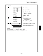
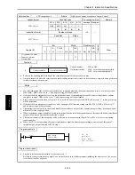
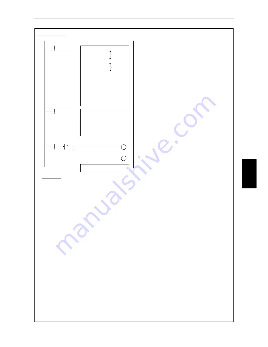
Sample program
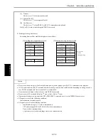
Description
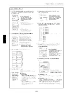
TRNS 0 parameter and sent data are configured at 1
st
scan by R7E3 contact.
When the switch is ON, execution bit R0 is ON, and data is sent out from CPU port.
TR
N
S
0
(
d, s, t)
R7E3
WM103 = 0
WM104 = H000A
WM105 = H0000
WM106 = 16
WM107 = H000A
WM108 = H0100
WM109 = 256
WM10A = 0
WM10B = H8002
WM10C = H800D
WM10D = 6
WM10E = 0
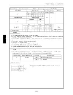
WR10 = H0200
FUN 5 (WR10)
R7E3 : 1
st
scan ON
Timeout = 0
Reserve area for data sending :
16 words from WR0
Reserve area for data receiving :
256 words from WR100
Data receiving definition
Start code : H02, End code : H0D
Communication speed : 19.2k bps
Format : 7 bits, even, 2 stop
Port 2 configured as general purpose port.
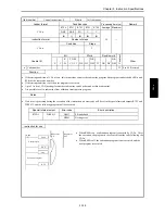
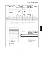
R7E3
WR100 = 9
WR101 = H0231
WR102 = H3830
WR103 = H3031
WR104 = H3338
WR105 = H0D00
Sent data : 9 bytes
Inverter (SJ300/L300P) command
FWD RUN for station No.18
02 31 38 30 30 31 33 38 0D
(STX 18 00 1 38 CR) [38=BCC]
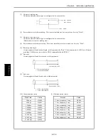
Switch
R0
TRNS 0 (WY10, WM100, R0)
When the switch is ON, execution bit R0 is ON, and
data is sent out from CPU port.
R5 enables data receiving from the other device.
WR0
WR100
DIF0
S
R5
S
Summary of Contents for HIDIC MICRO-EH
Page 1: ...HITACHI PROGRAMMABLE CONTROLLER APPLICATION MANUAL NJI 350B X ...
Page 12: ...MEMO ...
Page 14: ...Chapter 1 Features 1 2 MEMO ...
Page 50: ...Chapter 4 Product lineup and wiring 4 18 MEMO ...
Page 196: ...Chapter 5 Instruction Specifications 5 146 ...
Page 263: ...Chapter 11 Communication Specifications 11 10 MEMO ...

