Chapter 5 Instruction Specifications
5-138
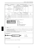
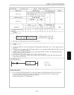
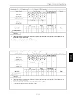
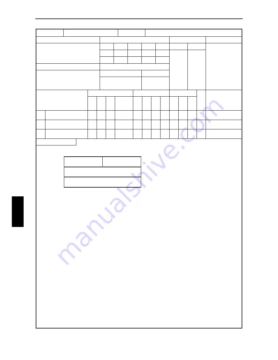
Item number
FUN instructions-13
Name
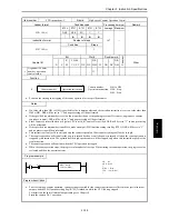
PWM Frequency on-duty changes
Ladder format
Condition code
Processing time (
µ
s)
Remark
R7F4
R7F3
R7F2
R7F1
R7F0
Average Maximum
FUN 148 (s)
DER
ERR
SD
V
C
↕
z
z
z
z
Instruction format
Number of steps
173
Condition
Steps
FUN 148 (s)
—
3
Bit
Word
Double word
Usable I/O
X
Y
R,
M
TD, SS,
CU, CT
WX WY
WR,
WM TC DX DY
DR,
DM
C
o
nstant
Other
s
Argument (PWM output
number)
{
s+1
Argument (Frequency
value)
{
s+2
Argument (On-duty
value)
{
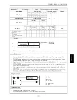
Function
PWM output number: H01 to H04
**: Disable area
Frequency: 10 to 2000 (Hz)
*: If the frequency value is set to less than 10 Hz, it is
internally changed to 10 Hz. The S parameter is also
rewritten.
On-duty value:
With auto correction – Depends on the frequency used.
Without auto correction – 0 to 100 (%)
Auto correction is executed when the value corresponding to
the CPU model is specified in WRF06B.
Caution: There will be a slight error even if correction setting
is performed
•
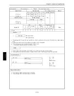
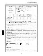
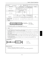
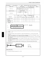
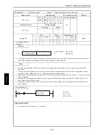
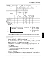
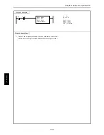
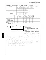
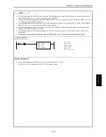
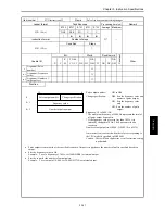
Sets the frequency value and on-duty value of the PWM output number specified by the on-duty value and the specified
frequency value.
•
Sets the frequency value in Hz.
Example: To set a frequency of 1 kHz, set 1000 (H3B8) as internal output.
•
Sets the on-duty value in %.
Example: To set an on-duty of 80 %, set 80 (H50) as internal output.
•
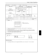
When the on-duty is set to be auto-corrected, the effective range of the on-duty is calculated using the following expressions.
On-duty lower limit value (%) = Hardware delay time (
µ
s) x Frequency used (Hz) x 10
-4
On-duty upper limit value (%) = 100
−
Hardware delay time (
µ
s) x Frequency used (Hz) x 10
-4
If the CPU model is EH-***DRP and the PWM output is 2 kHz,
On-duty lower limit value = 50 x 2000 x 10
-4
= 10 %
On-duty upper limit value = 100
−
(50 x 2000 x 10
-4
) = 90 %
Thus, the effective range of the on-duty will be 10 % to 90 %.
S
15
0
S + 1
Frequency values
S + 2
On-duty value
PWM number
**
8
7
FUN 148 (s
)
Summary of Contents for HIDIC MICRO-EH
Page 1: ...HITACHI PROGRAMMABLE CONTROLLER APPLICATION MANUAL NJI 350B X ...
Page 12: ...MEMO ...
Page 14: ...Chapter 1 Features 1 2 MEMO ...
Page 50: ...Chapter 4 Product lineup and wiring 4 18 MEMO ...
Page 196: ...Chapter 5 Instruction Specifications 5 146 ...
Page 263: ...Chapter 11 Communication Specifications 11 10 MEMO ...

