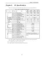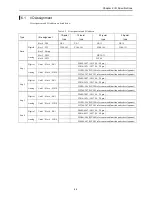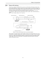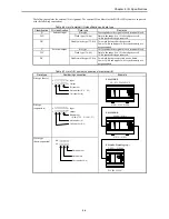
Chapter 5 Instruction Specifications
5-139
Notes
•
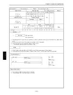
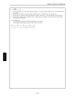
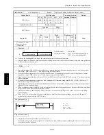
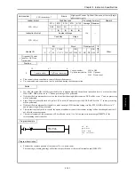
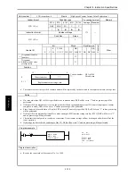
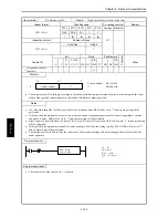
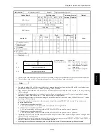
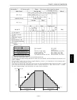
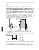
If a value other than H01 to H04 is specified as the PWM output number, and if the on-duty value is outside the effective
range, DER will be set to “1” and no processing will be performed.
•
If the external I/O corresponding to the PWM output number is set to a function other than PWM output, DER will be set to
“1” and no processing will be performed.
•
The settings made using the instruction will be reflected in the special internal output (WRF072 to WRF075 and WRF076 to
WRF079). However, it is not reflected if DER becomes equal to “1.”
•
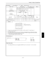
The minimum frequency that can be supported is 10 kHz. If a frequency value smaller than 10 kHz is specified, it will be
changed to 10 kHz internally by the system.
•
The maximum frequency that can be supported is 2 kHz. Do not set to more than 2 kHz. Operation above 2 kHz is not
guaranteed.
•
If the range for S exceeds the valid range of the I/O, DER will be set to “1” and no processing will be performed.
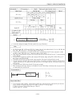
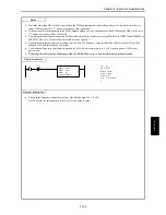
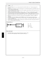
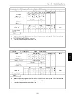
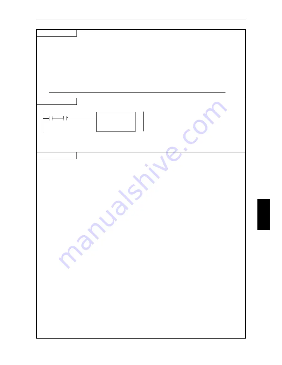
Program example
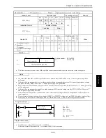
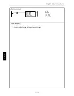
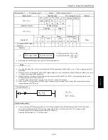
R8
LD
R8
AND DIF8
[
WR80 = H100
WR81 = 2000
WR82 = 30
FUN 148 ( WR80 )
]
DIF8
WR80 = H0100
WR81 = 2000
WR82 = 30
FUN 148 (WR80)
Program description
•
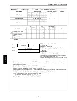
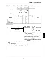
Sets both the frequency and on-duty value of the PWM output No. 1 (Y100).
Sets 2000 (Hz) for the frequency and 30 (%) for the on-duty value.
FUN 148 (s
)
Summary of Contents for HIDIC MICRO-EH
Page 1: ...HITACHI PROGRAMMABLE CONTROLLER APPLICATION MANUAL NJI 350B X ...
Page 12: ...MEMO ...
Page 14: ...Chapter 1 Features 1 2 MEMO ...
Page 50: ...Chapter 4 Product lineup and wiring 4 18 MEMO ...
Page 196: ...Chapter 5 Instruction Specifications 5 146 ...
Page 263: ...Chapter 11 Communication Specifications 11 10 MEMO ...


