Chapter 3 Function and Performance Specifications
3-3
No.
Item
Description
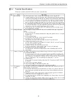
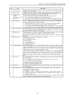
5
Control method
With the PLC, the user programs are converted in batch at operation startup, and the programs
after conversion will be executed in order as they are read one by one.
1] The method used for data I/O is that after the I/O data (information) is scanned (execution
from the head of the program to the end), it is updated in group. If refresh of external I/O is
required during scanning (refresh method), use the refresh instruction.
2] Apart from the program that will be normally executed, a periodic scan program which
interrupts the normal program at a fixed time intervals and is executed, can be created. The
time intervals are 10 ms, 20 ms and 40 ms.
3] The user programs are executed from the head of the program to the end, and are once again
repeated after performing the system processing that updates the lapsed timer value,
refreshes I/O, and performs communication with peripheral units.
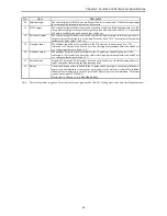
6
Run/stop control
Running and stopping the PLC is normally performed by the user.
1] Turn on the RUN switch to start operation for the 14-point type or higher. Turn this switch
off to stop operation.
For the 10-point type, turn on the RUN input terminal to start operation. Turn it off to stop
operation.
2] The start and stop operations can be performed with designated external inputs or internal
outputs by designating the operation control inputs with a programming unit.
3] Apart from the operation described above, if a malfunction is detected in the system while it
is running, operation stops and the outputs are aborted (OFF).
4] If the power is shut off and then turned back on while the system is running, operation starts.
When the power shuts off, turn off the power to the PLC, then shut off the external input
power. When turning the power back on, turn on the external input power before turning on
the power to the PLC.
5] When starting operation, do so after clearing internal information which is not designated
for storage during power failure. When stopping operation, leave the internal information as
is, turn off the outputs and then stop the operation.
6] When the power has been cut off for longer than the time allowed for the momentary power
failure, then depending on the system load status, either operation continues or the system
perceives that a power shut off has occurred and restarts operation. To resume operation
securely, have the power remain off for 1 minute or longer.
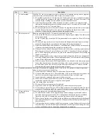
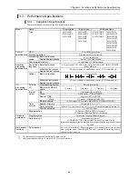
7
Operation parameters Each type of condition for operating the PLC can be set. The possible settings for operation
when an error occurs are provided below.
1] Operation may be continued when I/O information does not match.
2] Overload check time can be set. The initial value is 100 ms and the module stops when the
time for one scan takes longer than the set overload check time. (overload error)
3] Operation may be continued when an overload error occurs.
4] When a power failure (power shutoff) occurs, the internal output area for retaining
information and the timer counter range can be designated.
And, the setting below is possible.
1] The name of the user program can be registered.
2] A password can be set up so that the third party cannot reference the program.
3] It is necessary to register the type of I/O module used as an I/O assignment table. In order to
create this I/O assignment table, the types of I/O modules that are connected can be read.
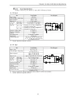
8
Change while in
operation
A part of a program can be modified during operation.
1] If a modification is made with a programming unit and a change is performed while in
operation, the user program in the CPU is changed and the altered program is switched
internally at the end of scanning, and operation continues with the new program.
2] When a control instruction is included in the modification to the program, make the changes
after first performing the control instruction change procedure in the programming unit to
check for safety.
3] Until operation starts to continue with the new program, a pause [halt period] occurs when
the module does not run. External input information is not being received during this time,
so leave a sufficient time for executing a change while in operation.
Summary of Contents for HIDIC MICRO-EH
Page 1: ...HITACHI PROGRAMMABLE CONTROLLER APPLICATION MANUAL NJI 350B X ...
Page 12: ...MEMO ...
Page 14: ...Chapter 1 Features 1 2 MEMO ...
Page 50: ...Chapter 4 Product lineup and wiring 4 18 MEMO ...
Page 196: ...Chapter 5 Instruction Specifications 5 146 ...
Page 263: ...Chapter 11 Communication Specifications 11 10 MEMO ...

