Chapter 3 Function and Performance Specifications
3-4
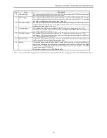
No.
Item
Description
9
Forced set/reset
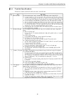
Forced set and forced reset of the designated I/O can be performed from the programming unit
connected to the CPU module.
10
Forced output
Output can be forced with respect to the designated I/O number from the programming unit
connected to the CPU module. For I/O that is not designated, outputs are shut off.
11
Calendar clock
function
(only for 23- and 28-
point types)
23-point and 28-point types have the calendar clock function.
1] The year, month, date, day of the week, hour, minute and second can be set.
2] There is a function for making adjustments in 30-second units.
3] When a battery is not installed, the calendar clock information is not retained when power
goes off. The calendar clock must be reset. (The battery is an optional. Purchase separately.)
12
Dedicated port
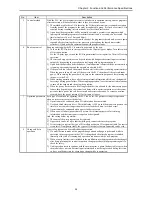
This is a communication port with dedicated protocol for the H-series. The communication
command called the task code is defined in the port.
1] A programming unit can be connected. (However, the command language programmer
PGM-CHH and the portable graph programmer PGM-GPH cannot be used.)
2] Port 1 and port 2 can be used as dedicated ports. Transmission speed, etc. can be switched
using the DIP switch. (Port 2 is supported only by the 23-point and 28-point type models.)
13
General purpose port General purpose port function is supported from software version H0130 (WRF051=H0130) or
newer. This function enables serial communication to any standard devices like bar code reader
by using TRNS/RECV command in user program.
14
Modem control
A modem can be used to connect externally. It becomes operable when data receives from the
external media, and task code communication can afterward be performed.
Port 1 can be assigned for this function by switching the DIP switch. (The 10-point type is not
supported.)
15
Self-diagnosis
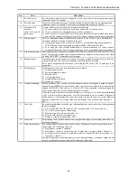
Self-diagnostic tests for the following items are performed:
1] Microcomputer check
2] System program area check
3] Memory check
4] User program check
5] Internal output area check
6] Mounted I/O check
16
Abnormal handling
When a problem occurs, the error code that indicates the error description is output to special
internal output WRF000 as a hexadecimal value. Also, errors are notified to the external devices
through the OK LED. If the error level is high, the CPU stops operation, but depending on the
error, the operation may be continued using the user settings.
If multiple errors occur, the error code with higher error severity is set. The detailed information
is also set to the special internal output. Also, this information is always recorded in the power
failure memory, so the information can be referenced even after the power is cut off. (However,
a battery is required.) The clearing of the error information can be conducted by turning on
R7EC.
17
Task code
By combining individual task codes, the following functions can be achieved by the programs in
the host computer:
1] CPU control (RUN/STOP control of CPU, occupy/release, CPU status read, etc.)
2] I/O control (various types of monitoring)
3] Memory write (all clear, batch transfer, etc.)
4] Memory read (reading of programs, etc.)
5] Response (various responses from CPU)
18
Instruction
Programming can be performed for various purposes and usage by combining Ladder and the
instruction language.
19
High-speed counter
The external input of the basic unit can be used as a high-speed counter by specifying it as a
counter input. The following can be set.
1] Single-phase counter, 2 channels
2] Single-phase counter, 4 channels (For the 10-point type, it is single-phase, 3 channels.)
3] Two-phase counter 1 channel, single-phase counter 1 channel (For the 10-point type, it is
two-phase, 1 channel.)
The functions include a count operation (up/down, leading/trailing), coincidence output control,
preset by preloaded input, and count value reading by strobe input.
Summary of Contents for HIDIC MICRO-EH
Page 1: ...HITACHI PROGRAMMABLE CONTROLLER APPLICATION MANUAL NJI 350B X ...
Page 12: ...MEMO ...
Page 14: ...Chapter 1 Features 1 2 MEMO ...
Page 50: ...Chapter 4 Product lineup and wiring 4 18 MEMO ...
Page 196: ...Chapter 5 Instruction Specifications 5 146 ...
Page 263: ...Chapter 11 Communication Specifications 11 10 MEMO ...


