Chapter 7 Programming
7-3
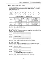
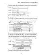
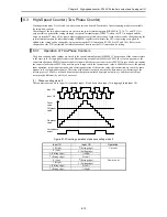
7.3
Programming Methods
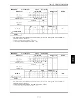
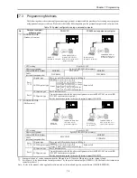
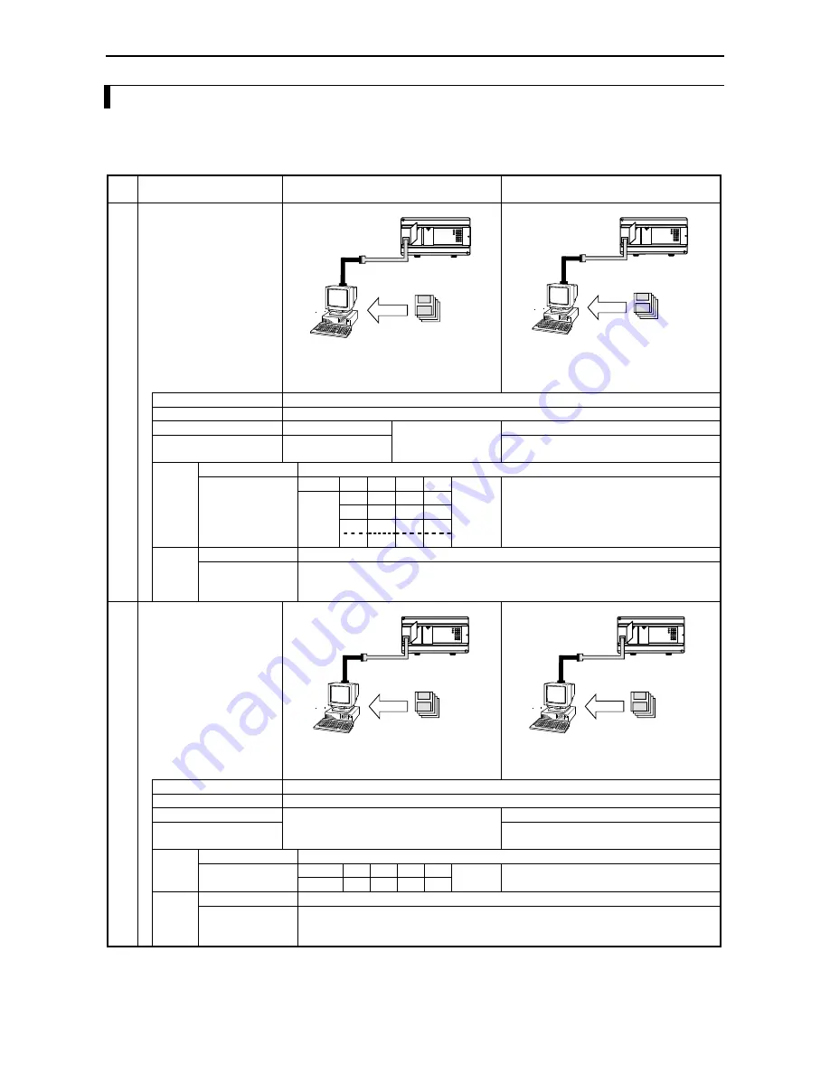
The following shows the system configuration using a personal computer and the procedures for creating a user program
using personal computer software. Please note that cables differ depending on the personal computer and software used.
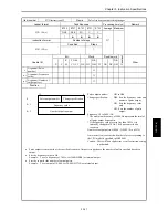
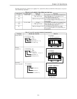
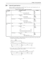
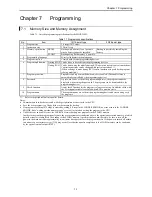
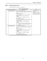
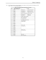
Table 7.3 System configuration using a personal computer
No.
Personal computer
software used
DOS/V PC
PC9800 series personal computer
1
LADDER EDITOR
(Windows
version)
DOS/V PC
(Windows
95/98/NT)
Install
LADDER EDITOR for
Windows
(HLW-PC3,
HLW-PC3E) system disks
(Japanese, English)
Install
PC9800 series PC
(Windows® 95/98/NT)
LADDER EDITOR for
Windows® (HLW-PC3)
system disks (Japanese)
CPU setting
Specify H-302.
Memory assignment
Specify RAM-04H (4 K memory).
Cable (MICRO-EH side)
EH-RS05
EH-VCB02
EH-RS05
Cable
(personal computer side)
WVCB02H
WPCB02H
10-point type
There are no DIP switches (fixed to 4800 bps).
DIP SW
1
2
3
4
ON
OFF ON
OFF 38.4 kbps
ON
OFF OFF OFF 19.2 kbps
OFF OFF ON
OFF 9600 bps
Port 1
*1, *2 14/23/28-point type
Status
OFF OFF OFF OFF 4800 bps
Same as left
10/14-point type
Port 2 does not exist.
Port 2
23/28-point type
Cannot be connected with the above configuration since the RS-422/485 are used (RS-
232C/422 converters are required.)
Set the transmission speed in the special internal output (WRF03D).
2
LADDER EDITOR
(DOS version)
DOS/V PC
(MS-DOS®)
Install
LADDER EDITOR DOS
version (HL-AT3E)
system disks (English)
Install
PC9800 series
PC (MS-DOS
®
)
LADDER EDITOR
DOS version (HL-PC3)
system disks (Japanese)
CPU setting
Specify H-302.
Memory assignment
Specify RAM-04H (4 k memory).
Cable (MICRO-EH side)
EH-RS05
Cable
(personal computer side)
EH-VCB02
PCCB02H
10-point type
There are no DIP switches (fixed to 4800 bps).
DIPSW
1
2
3
4
Port 1
*1, *2 14/23/28-point type
Status
OFF OFF OFF OFF 4800 bps
Same as left
10/14-point type
Port 2 does not exist.
Port 2
23/28-point type
Cannot be connected with the above configuration since the RS-422/485 are used (RS-
232C/422 converters are required.)
Set the transmission speed in the special internal output (WRF03D).
*1:
Settings of the port 1 can be changed when the DR signal is off. When the DR signal is on, the setting is fixed.
*2:
Set the port 1 to the transmission control procedure 1 by the special internal output (WRF01A). (The default is the transmission
control procedure 1.)
Note: Refer to the manual of the applicable software on how to install and operate each software (LADDER EDITOR).
Summary of Contents for HIDIC MICRO-EH
Page 1: ...HITACHI PROGRAMMABLE CONTROLLER APPLICATION MANUAL NJI 350B X ...
Page 12: ...MEMO ...
Page 14: ...Chapter 1 Features 1 2 MEMO ...
Page 50: ...Chapter 4 Product lineup and wiring 4 18 MEMO ...
Page 196: ...Chapter 5 Instruction Specifications 5 146 ...
Page 263: ...Chapter 11 Communication Specifications 11 10 MEMO ...


