Chapter 8 High-speed counter, PWM / Pulse train output and Analogue I/O
8-1
Chapter 8
High-speed counter, PWM / Pulse train
output and Analogue I/O
The MICRO-EH operates in four operation modes. By selecting the proper operation mode, input/output points can be assigned to
the counter input, interrupt input, pulse output, and PWM output functions, instead of the normal input/output function.
The 14-point type model or higher are equipped with two potentiometers. The values of internal outputs can be changed externally
using these potentiometers, without peripheral units.
The 23-point type model is equipped with two points of analogue input and one point of analogue output.
This chapter explains how to set various functions mentioned above, together with simple usage examples.
8.1
Input/Output Function
The normal input/output points can not only be used as they are, but can also be assigned special functions. In order to
assign these special functions, it is necessary to select the right operation mode; the following briefly explains the
procedure for selecting the operation modes. Refer to the section corresponding to each item for the details.
8.1.1
Initial Setting for Special Input/Output Function
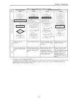
Figure 8.1 shows a flowchart for the setting procedures.
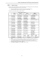
First, select an operation mode. There are 5 operation modes, mode 0 to 3 and 10. By selecting an operation mode the
input number to be used for high-speed counter input and the type of counter is determined, along with the output number
for the corresponding output.
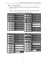
Next, the desired input/output function for each point of input/output should be selected, because the function assigned to
input/output varies depending on the operation mode selected.
Lastly, set the operating conditions for each input/output function selected.
Furthermore, performing the settings mentioned above does not in itself make the settings valid for the actual operation.
The settings become valid only after turning on the special internal output for individual setting (R7F5). After making the
settings valid, it is possible to make changes for each function using the special internal output for individual setting.
Turning the special internal output (R7F6) on also stores the settings performed above in the FLASH memory. From the
next time the power supply is turned on, the settings stored in the FLASH memory are automatically read; it is not
necessary to perform the settings every time.
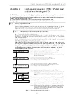
Figure 8.1 Flow of operation mode setting procedure
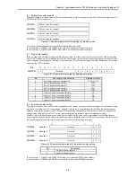
Set the number 0 to 3 corresponding to the mode you want to set in WRF070.
Refer to Table 8.1 for the details of each mode.
Note 1) If nothing is set, the settings stored in the FLASH memory become valid.
Note 2) If a number larger than 4 is set, mode 0 will be selected.
Note 3) After the settings are stored in the FLASH memory, it is not necessary to perform the settings
after step 1] from the next time.
Set the function of each input/output terminal in WRF071.
Refer to the section about detailed function settings for the details.
Note 4) If nothing is set, the initial value will become 0.
Set the operating conditions for each function in WRF072 to WRF07E.
Refer to the section about detailed operating condition settings for the details.
Note 5) If nothing is set, the initial value will become 0.
The settings performed in steps 1] to 3] become valid by turning R7F5 on.
Note 6) The settings performed in steps 1] to 3] do not become valid unless R7F5 is turned on while
output is turned off.
Moreover, if R7F5 is turned on while the CPU is running, the settings do not become valid
even though R7F5 is turned on. The settings become valid at the point when the CPU is
stopped.
The settings performed in steps 1] to 3] are stored in the FLASH memory by turning R7F6
on.
It is not necessary to perform the settings again when the power supply is turned on for the
next time.
Note 7) If R7F6 is not turned on, the settings will be changed to the ones stored in the FLASH
memory when the power supply is turned on for the next time (if nothing is stored in the
FLASH memory, the initial values will be set).
Note 8) When the CPU is operating, the settings are not stored in the FLASH memory by turning
R7F6 on.
Note 9) R7EF turns on while the settings are transferred to the FLASH memory. If the power supply
to the main unit is turned off while R7EF is on, the settings are not properly stored in the
FLASH memory; there is a possibility that the parameter settings are initialized when the
power supply is turned on for the next time.
1] Set the operation mode
3] Set the operating conditions
for each function
6] Store the settings in the memory.
2] Set input/output terminal
5] Change
individual setting
4] Make the settings valid
Summary of Contents for HIDIC MICRO-EH
Page 1: ...HITACHI PROGRAMMABLE CONTROLLER APPLICATION MANUAL NJI 350B X ...
Page 12: ...MEMO ...
Page 14: ...Chapter 1 Features 1 2 MEMO ...
Page 50: ...Chapter 4 Product lineup and wiring 4 18 MEMO ...
Page 196: ...Chapter 5 Instruction Specifications 5 146 ...
Page 263: ...Chapter 11 Communication Specifications 11 10 MEMO ...


