Chapter 8 High-speed counter, PWM / Pulse train output and Analogue I/O
8-12
(4)
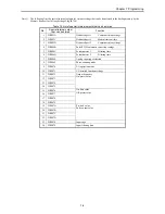
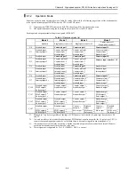
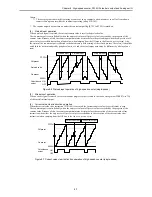
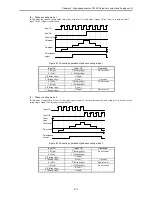
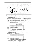
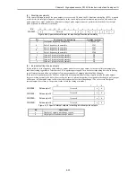
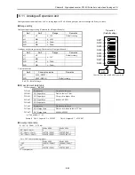
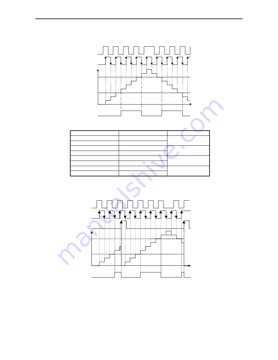
Phase counting mode 3
In this mode the counter counts at the rising and falling edge of input 1B. It counts up when input 1A is more ahead of
input 1B, and down when input 1A is lagging behind input 1B.
Figure 8.17 Counting operation of phase counting mode 3
Input 1A
Input 1B
Operation
1 (High)
↑
(Rising edge)
Up count
0 (Low)
↓
(Falling edge)
↓
(Falling edge)
1 (High)
Do not count
↑
(Rising edge)
0 (Low)
0 (Low)
↑
(Rising edge)
Down count
1 (High)
↓
(Falling edge)
↓
(Falling edge)
0 (Low)
Do not count
↑
(Rising edge)
1 (High)
(5)
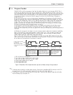
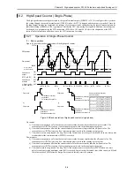
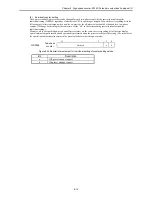
Clear input operation (common to all the phase counting modes)
The count value is cleared at the rising edge of input 1Z. As an example, the clear operation of phase counting mode 4 is
shown in Figure 8.18. (The clear operation works identically for all four phase counting modes.)
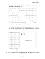
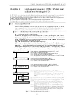
Figure 8.18 Count value clear operation (phase counting mode 4)
Coincidence
output
On preset
Off preset
Count
value
Input 1B
Input 1A
Coincidence
output
On preset
Off preset
Count
value
Input 1Z
Input 1B
Input 1A
Summary of Contents for HIDIC MICRO-EH
Page 1: ...HITACHI PROGRAMMABLE CONTROLLER APPLICATION MANUAL NJI 350B X ...
Page 12: ...MEMO ...
Page 14: ...Chapter 1 Features 1 2 MEMO ...
Page 50: ...Chapter 4 Product lineup and wiring 4 18 MEMO ...
Page 196: ...Chapter 5 Instruction Specifications 5 146 ...
Page 263: ...Chapter 11 Communication Specifications 11 10 MEMO ...

