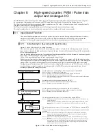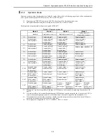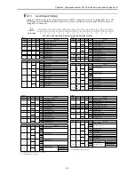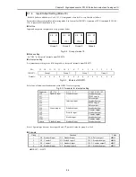
Chapter 8 High-speed counter, PWM / Pulse train output and Analogue I/O
8-15
8.4
PWM Output
A PWM output can be set as an output by setting the operation mode and output terminal. By setting an output to a PWM
output, a pulse with a duty ratio in the range that corresponds to the specified frequency can be output.
8.4.1
Operation of PWM Output
The PWM output settings are stored in the special internal outputs. It is only possible to perform the settings through the
special internal output when the CPU is stopped and the output is turned off. Once all the input/output settings are
completed, the setting of each PWM output can be changed using the special internal outputs for individual setting,
regardless of whether the CPU is operating or stopped. In addition, the settings can be changed by a program using the
FUN instruction (FUN148). See the chapter about the FUN instruction for information about how to use the FUN
instruction for setting.
(1)
Basic operation
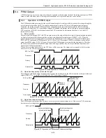
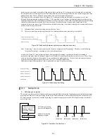
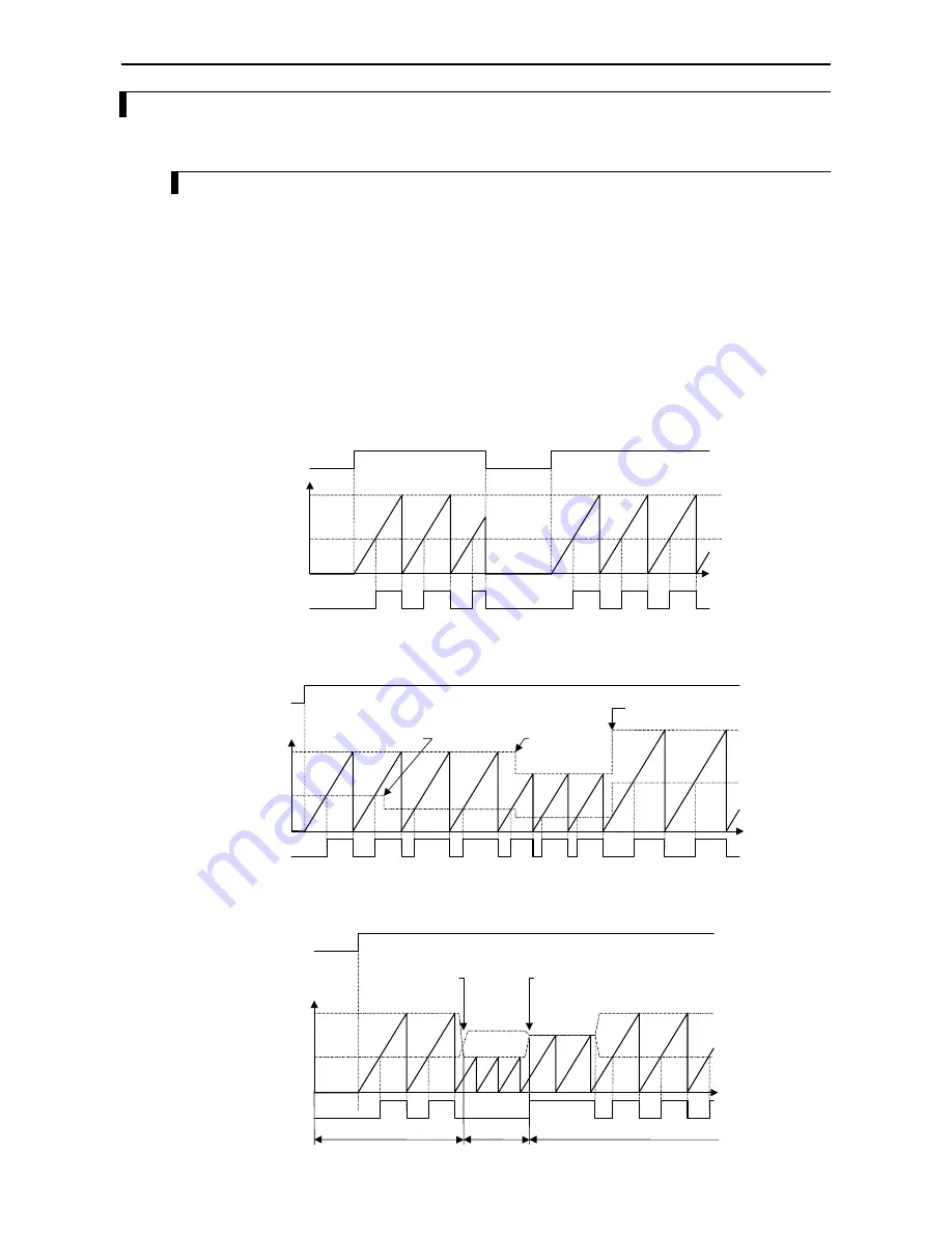
The special internal outputs R7FC to R7FF are used to control the output. When these special internal outputs are turned
on, a pulse is output at the frequency and the on-duty set in the special internal outputs (WRF072 to 79). When the
special internal output for output control is turned off, the PWM output is also turned off. The special internal outputs
R7FC to R7FF correspond to PWM outputs 1 to 4 (Y100 to Y103); for example, if R7FD is turned on, a pulse train is
output from PWM output 2 (Y101). The on/off status of the PWM outputs is not stored in the data memory. Therefore,
the status of the terminals used for PWM output monitored by peripheral units, etc. may be different from the actual
status of the PWM output terminals.
When a fatal or serious error occurs in the CPU, there will be no output. The output is also stopped if a fatal or serious
error occurs in the CPU during output.
t
R7FC to R7FF
Output pulse
On duty
Frequency
Figure 8.25 Basic operation of PWM output
(2)
Operation when setting values are changed
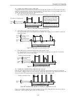
The settings of each PWM output (frequency and on-duty) can be changed by the FUN instruction or the special internal
outputs (WRF072 to 79) regardless of whether the CPU is operating or stopped.
R7FC to R7FF
Output pulse
Change in
frequency
Change in both
frequency and
On duty
Change in On duty
On duty
Frequency
t
Figure 8.26 Operation of PWM output when setting values are changed.
(3)
Operation at abnormal settings
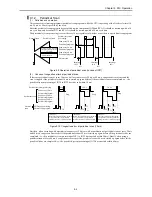
The PWM output is not output if the on-duty is set to a value other than the range in use. However, the FUN instruction
does not execute setting change when the setting value is abnormal.
t
R7FC to R7FF
Output pulse
On duty
Normal settings
Abnormal
settings
Normal settings
Frequency
On-duty setting value:
within the range
On-duty setting value:
exceeding the range
Figure 8.27 Operation of PWM output at abnormal settings
Summary of Contents for HIDIC MICRO-EH
Page 1: ...HITACHI PROGRAMMABLE CONTROLLER APPLICATION MANUAL NJI 350B X ...
Page 12: ...MEMO ...
Page 14: ...Chapter 1 Features 1 2 MEMO ...
Page 50: ...Chapter 4 Product lineup and wiring 4 18 MEMO ...
Page 196: ...Chapter 5 Instruction Specifications 5 146 ...
Page 263: ...Chapter 11 Communication Specifications 11 10 MEMO ...

