Chapter 8 High-speed counter, PWM / Pulse train output and Analogue I/O
8-19
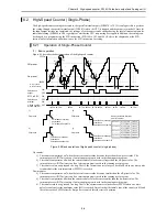
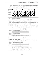
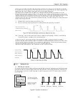
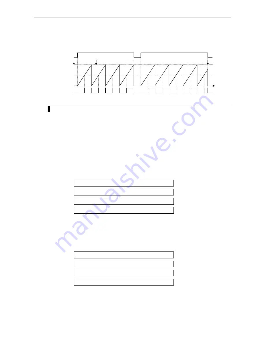
To change the number of output pulses, the following operation will be performed:
1] When the number of pulses is to be changed to a value larger than the number of pulses currently being output,
pulses will be output until the number of newly changed pulses is reached, and then the pulse output stops.
2] When the number of pulses is to be changed to a value smaller than the number of pulses currently being output,
the pulse output stops when the current number of pulses is reached.
t
2]
1]
R7FC to R7FF
Output pulse
Frequency/2
Change of the number
of pulses 6
→
3
Change of the number
of pulses 2
→
4
Frequency
Figure 8.33 Operation for changing the number of pulse output
8.5.2
Setting of Pulse Output
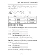
The settings of the pulse outputs are stored in the special internal outputs (WRF072 to WRF07D).
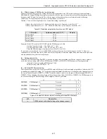
(1)
Setting the pulse output frequency
Set the frequency of the output pulse for each pulse output to be used in all of the special internal outputs shown below.
The setting values are 10 to 5000 (HA to H1388). If a value less than 10 Hz is set, it is internally changed to 10 Hz by the
system. When setting the frequencies, make sure that the total value of all pulse output frequencies stays within 5 kHz.
(Example 1)
Assuming there is one point of pulse output and the output frequency is 5 kHz:
Setting value = 5000 (H1388)
(Example 2)
Assuming there are three points of pulse output and the output frequencies are 1 kHz, 1 kHz, and 3 kHz,
respectively (the settings should be made so that the sum of the output frequencies set for each of the
pulse outputs becomes 5 kHz or less.):
Setting value = 1000 (H3E8)
Setting value = 1000 (H3E8)
Setting value = 3000 (HBB8)
WRF072:
Output frequency for pulse output 1
WRF073:
Output frequency for pulse output 2
WRF074:
Output frequency for pulse output 3
WRF075:
Output frequency for pulse output 4
Figure 8.34 Special internal outputs for setting output frequencies
In case of mode 1, WRF072 and WRF073 are used for setting the on-preset value of a counter.
In case of mode 4, WRF072 and WRF075 are used for setting the on-preset value of a counter.
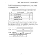
(3)
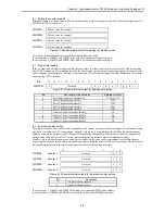
Setting the number of output pulses
Set the number of output pulses for each pulse output used. The setting values are 0 to 65535 (H0 to HFFFF). If the
number of output pulses is set to “0,” no pulses will be output.
WRF07A:
Number of output pulses for pulse output 1
WRF07B:
Number of output pulses for pulse output 2
WRF07C:
Number of output pulses for pulse output 3
WRF07D:
Number of output pulses for pulse output 4
Figure 8.35 Special internal outputs for setting number of output pulses
In case of mode 1, WRF07A and WRF07B are used for setting the preload strobe value.
In case of mode 4, WRF07A and WRF07D are used for setting the preload strobe value.
Summary of Contents for HIDIC MICRO-EH
Page 1: ...HITACHI PROGRAMMABLE CONTROLLER APPLICATION MANUAL NJI 350B X ...
Page 12: ...MEMO ...
Page 14: ...Chapter 1 Features 1 2 MEMO ...
Page 50: ...Chapter 4 Product lineup and wiring 4 18 MEMO ...
Page 196: ...Chapter 5 Instruction Specifications 5 146 ...
Page 263: ...Chapter 11 Communication Specifications 11 10 MEMO ...


