Chapter 8 High-speed counter, PWM / Pulse train output and Analogue I/O
8-20
(4)
At setting abnormality
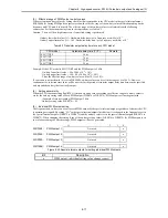
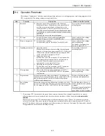
If the sum of the frequencies of the pulse outputs is set to exceed 5 k when the PI/O function setting flag (R7F5) is turned
on, the bit for the total pulse frequency abnormality in the error display special internal output turns on, and none of the
pulse outputs are output. In addition, individual setting of pulse outputs cannot be performed when the bit for the total
pulse frequency abnormality is turned on.
Bit:
15
14
13
12
11
10
9
8
7
6
5
4
3
2
1
0
WRF057:
a
Not used
b
c
d
e
f
g
h
i
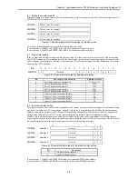
Figure 8.36 Special internal output for input/output function abnormality
Bit
Description of abnormality
Related terminal
a
Total pulse frequency abnormality
Y100 to Y103
b
Pulse 4 frequency abnormality
Y103
c
Pulse 3 frequency abnormality
Y102
d
Pulse 2 frequency abnormality
Y101
e
Pulse 1 frequency abnormality
Y100
f
Counter 4 preset value abnormality
X6
g
Counter 3 preset value abnormality
X4
h
Counter 2 preset value abnormality
X2
i
Counter 1 preset value abnormality
X0
(5)
Individual setting of pulse outputs
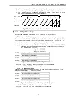
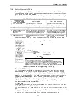
It is possible to set the frequency and number of output pulses for each pulse output by the special internal outputs for
individual setting, regardless of whether the CPU is operating or stopped. Turn on the corresponding bit in the following
special internal outputs when only the pulse frequency or number of output pulses should be changed.
If the total of frequencies exceeds 5 kHz as a result of performing individual setting of pulse outputs for pulse outputs
that are working normally, the bit for the error display special internal output that corresponds to the changed pulse output
will turn on, and that pulse output will work at the frequency before the setting change. (The value set in the special
internal output also returns to the previous value before the setting was made.)
15 2
1
0
WRF058:
Pulse output 1
Not used
a
b
WRF059:
Pulse output 2
Not used
a
b
WRF05A:
Pulse output 3
Not used
a
b
WRF05B:
Pulse output 4
Not used
a
b
Figure 8.37 Special internal outputs for setting individual pulse outputs
Bit
Description
a
Number of output pulse change request
b
Output pulse frequency change request
Summary of Contents for HIDIC MICRO-EH
Page 1: ...HITACHI PROGRAMMABLE CONTROLLER APPLICATION MANUAL NJI 350B X ...
Page 12: ...MEMO ...
Page 14: ...Chapter 1 Features 1 2 MEMO ...
Page 50: ...Chapter 4 Product lineup and wiring 4 18 MEMO ...
Page 196: ...Chapter 5 Instruction Specifications 5 146 ...
Page 263: ...Chapter 11 Communication Specifications 11 10 MEMO ...

