Chapter 8 High-speed counter, PWM / Pulse train output and Analogue I/O
8-21
8.6
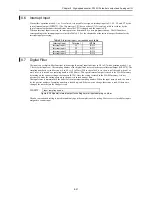
Interrupt Input
When either operation mode 0, 1, or 3 is selected, it is possible to assign an interrupt input to X1, X3, X5, and X7 by the
special internal output (WRF07F). (The 10-point type CPU does not have X7.) It is only possible to set them by the
special internal output under the conditions where the CPU is stopped and the output is off.
When an interrupt input is entered, an interrupt process determined by a user program starts up. The INT numbers
corresponding to the interrupt inputs are listed in Table 8.2. See the chapter about the instruction specifications for the
interrupt input processing.
Table 8.3 Interrupt input – correspondence table
Interrupt input
Terminal
INT No.
Interrupt input 1
X1
INT16
Interrupt input 2
X3
INT17
Interrupt input 3
X5
INT18
Interrupt input 4
X7
INT19
8.7
Digital Filter
The input can set digital filter functions (when assigned normal input functions in X0 to X7 with operation mode 0, 1, or
3, be set to the input too). The sampling number of the digital filter is stored in the special internal output (WRF07F). The
sampling number is set in 0.5ms unit (0 to 40, i.e., 0 to 20ms). When the value 0 is set, there is no filter, and when 41 or
more is set, it is treated as a sampling number of 40 (20ms). This special internal output is stored in the FLASH memory
by turning on the various setting write requests (R7F6). Once the setting is stored in the FLASH memory, it is not
necessary to make the setting again when the power is turned on next time.
The input status is maintained in the buffer for the maximum sampling number. When the input status is read, the status
for the past set number of sampling numbers is looked up, and if there was no change, that status is read. If there were
changes, the status before the change is read.
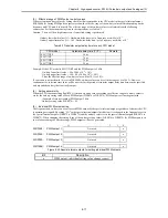
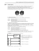
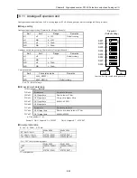
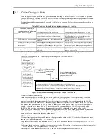
WRF07F:
Input sampling number
Figure 8.38 Special internal output for setting normal input sampling number
The above-mentioned setting is stored immediately upon the completion of the setting. Moreover, it is invalid for inputs
assigned to counter input.
Summary of Contents for HIDIC MICRO-EH
Page 1: ...HITACHI PROGRAMMABLE CONTROLLER APPLICATION MANUAL NJI 350B X ...
Page 12: ...MEMO ...
Page 14: ...Chapter 1 Features 1 2 MEMO ...
Page 50: ...Chapter 4 Product lineup and wiring 4 18 MEMO ...
Page 196: ...Chapter 5 Instruction Specifications 5 146 ...
Page 263: ...Chapter 11 Communication Specifications 11 10 MEMO ...

