Chapter 9 PLC Operation
9-1
Chapter 9
PLC Operation
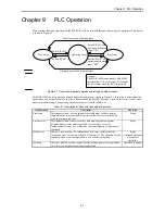
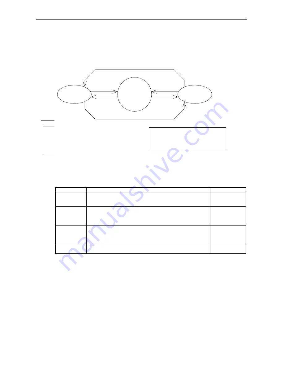
The operating status and stop status of the MICRO-EH can be switched through various types of operations. This feature
is shown in Figure 9.1.
Stop status
Switch “STOP” or
operation definition
input “OFF”
Switch “RUN” and
operation definition
input “ON”
Switch “STOP”
Switch “RUN”
Designate operation definition input
Cancel operation definition input
Stop status
Operating status
Caution
The MICRO-EH cannot handle a REMOTE
specification. A 10-point type CPU becomes
the RUN mode when the RUN input is On.
Figure 9.1 Transitional diagram between operating and stop statuses
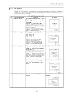
The MICRO-EH can be operated or stopped under the conditions as shown in Figure 9.1. If an error is detected during
operation or stop, output is shut off, an error is displayed and the MICRO-EH stops. There are fatal error, serious error,
minor error and warning. The operating status for each error is listed in Table 9.1.
Table 9.1 Description of each error and operating status
Classification
Description
Run/Stop
Fatal error
This indicates there is a fatal and unrecoverable error, such as a power
supply problem, microcomputer error, system ROM error, system RAM
error and system path error.
Stops
Serious error
This indicates there is an error such as data memory problem, system
program problem, user memory problem, user memory size error,
syntax/assembler error, etc., which may cause a malfunction if operation is
continued.
Stops
Minor error
These are errors such as I/O information verify error, remote problem,
congestion error, excessively assigned I/O points, etc. The operation may be
continued when a continue operation is set by the user programs.
Stops
(continued operation
is possible if
specified)
Warning
These are problems such as a transfer error, backup memory write problem,
etc. where it is possible to continue the operation.
Operation continues
Summary of Contents for HIDIC MICRO-EH
Page 1: ...HITACHI PROGRAMMABLE CONTROLLER APPLICATION MANUAL NJI 350B X ...
Page 12: ...MEMO ...
Page 14: ...Chapter 1 Features 1 2 MEMO ...
Page 50: ...Chapter 4 Product lineup and wiring 4 18 MEMO ...
Page 196: ...Chapter 5 Instruction Specifications 5 146 ...
Page 263: ...Chapter 11 Communication Specifications 11 10 MEMO ...

