Chapter 11 Communication Specifications
11-6
(2)
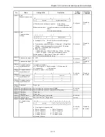
List of commands (extract)
1]
AT commands
Command
Function overview
Example
AT
Automatically recognizes data format
A/
Re-executes the response directly preceding
ATA
Forced reception
ATDmm
Dial
ATD12345678
ATEn
Command echo (echo back a text string entered to modem)
0: No
1: Yes
ATE0
ATHn
Line ON/OFF
0: On hook (disconnect)
1: Off hook
ATH0
ATH1
ATPn
Pulse (dial) setting
0, 1: 10 pps
2 : 20 pps
ATP0, ATP1
ATP2
ATQn
Result code setting 0: Yes 1: No
ATQ0
ATT
Tone (push) setting
ATT
ATSn = X
Sets S register value.
ATS0 = 0
ATVn
Result code display format
0: Number
1: Word
ATV0
ATV1
AT&Cn
CD signal control
0: Always on
1: Depends on the carrier of counter-party modem
AT&C0
AT&C1
AT&Dn
ER signal control
0: Always on
2: Turning from on to off during communication disconnects line
3: Turning from on to off resets the software
AT&D0
AT&D2
AT&D3
AT&Sn
DR signal
0: Always on
1: Depends on sequence
2: Depends on CD signal
AT&S0
AT&S1
AT&S2
AT&Rn
RI(CI) signal control
0: Turns on from calling start until communication begins
1: Turns on from calling start until communication ends
2: Turns on/off in synchronization with the call signal
AT&R0
AT&R1
AT&R2
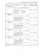
2]
S register
S register
Set value
Function
S0
0 no automatic
reception
1 to 255
Setting for automatic reception/reception ring count
S2
0 to 127
(43 [+] )
Escape code setting
S3
0 to 127
(13 [CR] )
CR code setting
S4
0 to 127
(10 [LF] )
LF code setting
3]
Result codes
Number format
Word format
Meaning
0
OK
Normal execution
1
CONNECT
Connection complete
2
RING
Reception detected
3
NO CARRIER
Line disconnected
4
ERROR
Command error
5
CONNECT 1200
1200 bps connection
6
NO DIAL TONE
Cannot hear dial tone
7
BUSY
Busy signal detected
8
NO ANSWER
No tone heard
10
CONNECT 2400
2400 bps connection
11
CONNECT 4800
4800 bps connection
12
CONNECT 9600
9600 bps connection
13
CONNECT 14400
14400 bps connection
Summary of Contents for HIDIC MICRO-EH
Page 1: ...HITACHI PROGRAMMABLE CONTROLLER APPLICATION MANUAL NJI 350B X ...
Page 12: ...MEMO ...
Page 14: ...Chapter 1 Features 1 2 MEMO ...
Page 50: ...Chapter 4 Product lineup and wiring 4 18 MEMO ...
Page 196: ...Chapter 5 Instruction Specifications 5 146 ...
Page 263: ...Chapter 11 Communication Specifications 11 10 MEMO ...

