Chapter 12 Error Code List and Special Internal Outputs
12-5
12.4 Bit Special Internal Output Area
The MICRO-EH has a special internal output area for performing status display and various other settings. The special
internal output area is constantly backed up in case of power failure.
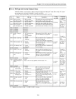
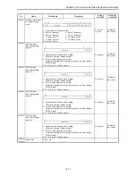
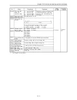
The following lists the definitions of the bit special internal output area (R7C0 to R7FF).
No.
Name
Meaning
Description
Setting
condition
Resetting
condition
R7C0 Ignore scan time
error (normal scan)
0: Stop operation
1: Continue operation
Designates continue/stop running when
a normal scan overload error occurs
R7C1 Ignore scan time
error (cyclic scan)
0: Stop operation
1: Continue operation
Designates continue/stop running when
a periodic-scan overload error occurs
Set by user
R7C2 Ignore scan time
error (interrupt scan)
0: Stop operation
1: Continue operation
Designates continue/stop running when
an interrupt-scan overload error occurs
Cleared by
user, Cleared
when
retentive area
is cleared, or
the CPU is
initialized.
R7C3 Undefined
Do not use.
R7C4 Undefined
Do not use.
R7C5 Undefined
Do not use.
R7C6 Undefined
Do not use.
R7C7 On line change in
RUN
0: On line changed not
allowed.
1: On line changed
allowed.
Designates whether online change in
RUN is allowed in user program
Set by user
R7C8 Serious error flag
0: Normal
1: Abnormal
Indicates whether there is an abnormal
in the microcomputer
(Address error, undefined instruction)
R7C9 Microcomputer error 0: Normal
1: Abnormal
Indicates whether there is an abnormal
in the microcomputer
(Computation error)
R7CA User memory error
0: Normal
1: Abnormal
Indicates whether there is an abnormal
in user memory
Set by the
system
Cleared by
user, Cleared
when
retentive area
is cleared, or
the CPU is
initialized.
R7CB Undefined
Do not use.
R7CC Memory size over
0: Normal
1: Abnormal
Indicates whether the capacity set by
the parameter exceeds loaded memory
capacity
R7CD I/O configuration
error
0: Normal
1: Unmatched
Indicates whether I/O assignment and
loading are matched (Mismatched
information output to WRF002)
Set by the
system
Cleared by
user, Cleared
when
retentive area
is cleared, or
the CPU is
initialized.
R7CE Undefined
Do not use.
R7CF
*1
Operation mode for
instantaneous power
failure
0: Hold
1: Reset (same start up operation as normal power on.)
Set by the
system
Cleared by
user, Cleared
when retentive
area is cleared,
or the CPU is
initialized.
R7D0 Undefined
Do not use.
R7D1 Scan time error
(normal scan)
0: Normal
1: Scan time over
Indicates whether the normal scan
execution time has exceeded the
designated time
R7D2 Scan time error
(cyclic scan)
0: Normal
1: Scan time over
Indicates whether the periodic scan was
completed within cycle time
R7D3 Scan time error
(interrupt scan)
0: Normal
1: Scan time over
Indicates whether an interrupt of the
same factor occurred during interrupt
scan execution.
R7D4 Grammar/assemble
error
0: Normal
1: Error
Indicates whether there is a grammar
error in user program (Detailed
information output to WRF001)
Set by the
system
Cleared by
user, Cleared
when
retentive area
is cleared, or
the CPU is
initialized.
R7D5 Blown fuse detection 0: Normal
1: Error
Indicates whether or not a fuse
connected to the second pin (see
Chapter 11) of serial port 1 has blown
out.
Set by the
system
Cleared by
the system
R7D6 Undefined
Do not use.
*1:
Supported by software version 1.11 (WRF051=H0111) or newer.
Summary of Contents for HIDIC MICRO-EH
Page 1: ...HITACHI PROGRAMMABLE CONTROLLER APPLICATION MANUAL NJI 350B X ...
Page 12: ...MEMO ...
Page 14: ...Chapter 1 Features 1 2 MEMO ...
Page 50: ...Chapter 4 Product lineup and wiring 4 18 MEMO ...
Page 196: ...Chapter 5 Instruction Specifications 5 146 ...
Page 263: ...Chapter 11 Communication Specifications 11 10 MEMO ...

