Chapter 12 Error Code List and Special Internal Outputs
12-6
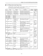
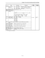
No.
Name
Meaning
Description
Setting
condition
Resetting
condition
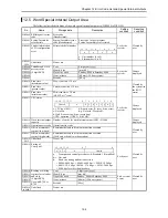
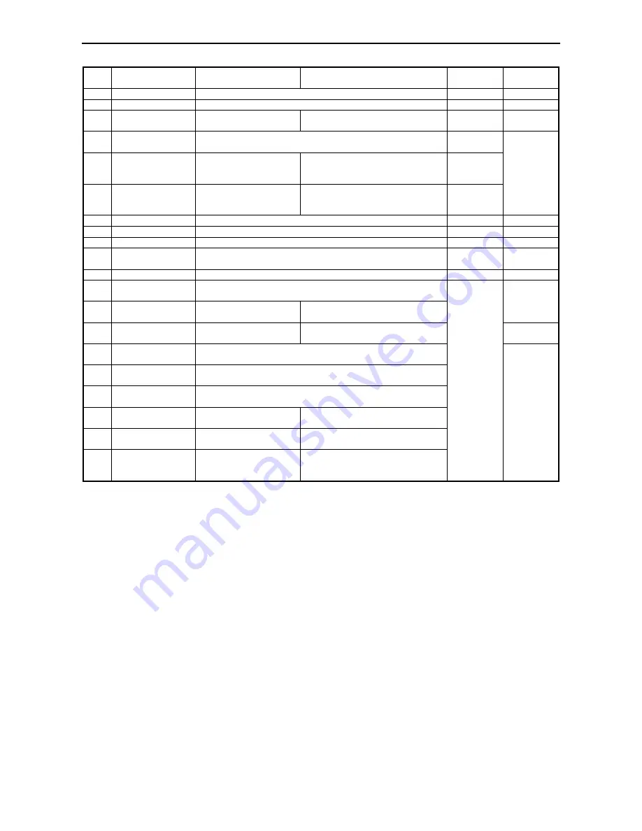
R7D7 Undefined
Do not use.
R7D8 Undefined
Do not use.
R7D9
Battery error
0: Normal
1: Abnormal
Indicates whether battery voltage is
low
Set by the
system
Cleared by
the system *2
R7DA
*1
Instantaneous power
failure detection
0: Not detected
1: Instantaneous power failure detected.
Set by the
system
R7DB
Self-diagnostic error
0: Normal
1: Error
Indicates whether there is a self-
diagnostic error (Detailed information
output to WRF000)
Set by the
system
R7DC
Output mode
0: Stops output
1: Continues output
Operation mode at CPU stop for PWM
output, pulse output and counter
coincidence output.
Set by user
Cleared by
user, Cleared
when
retentive area
is cleared, or
the CPU is
initialized.
R7DD Undefined
Do not use.
R7DE Undefined
Do not use.
R7DF Undefined
Do not use.
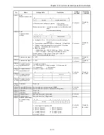
R7E0 Key switch location
(STOP)
0: at RUN position
1: at STOP position
Set by the
system
Cleared by
the system
R7E1 Undefined
Do not use.
R7E2 Key switch location
(RUN)
0: at STOP position
1: at RUN position
R7E3 1
st
scan ON after
RUN
1: 1
st
scan after RUN
ON only at the 1
st
scan.
Cleared by
the system
R7E4
Always ON
1: Always
Always ON regardless of CPU status
Cannot be
cleared.
R7E5
0.02 second clock
0: 0.01 seconds
1: 0.01 seconds
R7E6
0.1 second clock
0: 0.05 seconds
1: 0.05 seconds
R7E7
1.0 second clock
0: 0.5 seconds
1: 0.5 seconds
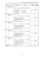
R7E8
CPU Occupation
0: Unoccupied
1: Occupied
Indicates CPU occupation status from
the peripheral unit
R7E9
RUN prohibited
0: Operation allowed
1: Operation prohibited
Indicates whether it is operation
prohibited status
R7EA
Executing a online
change in RUN
1: Being executed
Indicates whether operation is
temporarily stopped (output hold) due
to online change in RUN
Set by the
system
Cleared by
the system
*1:
Supported by software version 1.11 (WRF051=H0111) or newer.
*2:
The battery error (R7D9) will turn off when the error cause is eliminated by replacing the battery, etc.
Summary of Contents for HIDIC MICRO-EH
Page 1: ...HITACHI PROGRAMMABLE CONTROLLER APPLICATION MANUAL NJI 350B X ...
Page 12: ...MEMO ...
Page 14: ...Chapter 1 Features 1 2 MEMO ...
Page 50: ...Chapter 4 Product lineup and wiring 4 18 MEMO ...
Page 196: ...Chapter 5 Instruction Specifications 5 146 ...
Page 263: ...Chapter 11 Communication Specifications 11 10 MEMO ...

