Chapter 12 Error Code List and Special Internal Outputs
12-10
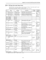
No.
Name
Storage data
Description
Setting
condition
Resetting
condition
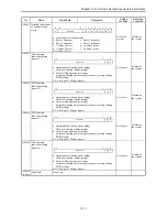
WRF03C
Port 1
Modem timeout time
a: Whether or not settings are present
0=No setting
1=Setting is present
Modem timeout time: 1 second increments (set with hexadecimal
value)
0=No timeout monitoring
Set by user
Cleared by
user
WRF03D
Port 2
Communication
settings
a: Setting bit 1=Set
Set to 0 by the system after setting is
complete.
b: Transmission control procedures 0=Standard, 1=Simplified
c: Whether or not station numbers are present 0=No station
numbers, 1=Station numbers are present
d: Baud rate settings
= 00000: 4800 bps, = 00001: 9600 bps, = 00010: 19.2 kbps
= 00011: 38.4 kbps, = 4800 bps if other than the above
Station numbers: 2 digits from 00 through 31 of BCD
Set to 31 for values outside the range
Set by user
Cleared by
user
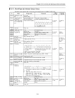
WRF03E
Potentiometer input 1 0 - 1023
Set by user
Cleared by
user
WRF03F
Potentiometer input 2 0 - 1023
Set by user
Cleared by
user
WRF040
to F042
Occupied member
registration area 1
WRF043
to F045
Occupied member
registration area 2
WRF046
to F048
Occupied member
registration area 3
WRF049
to F04B
Occupied member
registration area 4
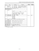
Occupied port number
a: 0=Not occupied, 1=Read-occupied, 2=Write-occupied
b: Loop number
c: Unit number
d: Module number e: Port number
Set by the
system
Cleared by
the system
WRF04C
to F04F
Undefined
Do not use.
WRF050
System ROM version System software version in internal ROM
WRF051
System ROM version System software version in external FLASH memory
Set by the
system
-
WRF052
Undefined
Do not use.
WRF053
Undefined
Do not use.
WRF054
Power on timer
Power on time [sec.] (low word)
WRF055
Power on timer
Power on time [sec.] (high word)
Set by the
system
-
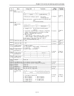
WRF057
Detailed information
of counter setting
errors
a: Error in pulse frequency total
b: Pulse 4 frequency
c: Pulse 3 frequency
d: Pulse 2 frequency
e: Pulse 1 frequency
f: Counter 4 preset
g: Counter 3 preset
h: Counter 2 preset
i: Counter 1 preset
0=Normal, 1=Error
Set by the
system
Cleared by
the system
15
8
7
0
a
Not used
Modem timeout time
15 14 13 12
8
7
0
a
b
c
d
Station number
15
8
7
0
a
Fixed to 0
b
c
d
e
15 14
8
7
6
5
4
3
2
1
0
a
Not used
b
c
d
e
f
g
h
i
Summary of Contents for HIDIC MICRO-EH
Page 1: ...HITACHI PROGRAMMABLE CONTROLLER APPLICATION MANUAL NJI 350B X ...
Page 12: ...MEMO ...
Page 14: ...Chapter 1 Features 1 2 MEMO ...
Page 50: ...Chapter 4 Product lineup and wiring 4 18 MEMO ...
Page 196: ...Chapter 5 Instruction Specifications 5 146 ...
Page 263: ...Chapter 11 Communication Specifications 11 10 MEMO ...


