Chapter 13 Troubleshooting
13-6
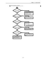
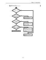
13.3 Procedures to Solve Abnormality
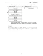
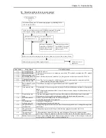
The following shows the processing flow when a problem has occurred:
Problem occurred
Bring the system to a safe condition
Record the status
Problem, Analysis, Presumption
Major problems
Verification points
Typical causes of problem
Reference
item
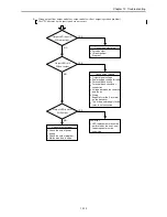
PLC will not start
Power LED, CPU error
code
Power supply problem, power shut-off,
insufficient power supply capacity, fatal CPU
error
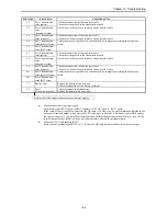
(a)
Will not operate
(will not RUN)
CPU error code, CPU
LED, Internal output of
error
I/O assignment problem, incorrect parameter
settings, incorrect user program, syntax error,
operating conditions not established, write-
occupied status
(b)
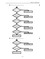
Operation stopped
(RUN stopped)
Power LED, CPU LED,
CPU error code
Power supply problem, expansion power supply
problem/shut-off, CPU problem, memory
problem
(c)
Erroneous input, no input
(abnormal operation)
CPU LED, I/O LED
Monitoring by peripheral
units
User program timings, input power supply, bad
connection, problem in input area, I/O inductive
noise
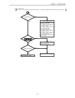
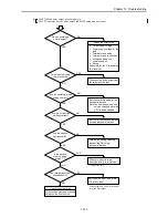
(d)
Counter input does not
operate
Input LED, special
internal output setting
Input power supply, bad connection, problem in
input area, I/O inductive noise, operating mode
setting error
(e)
Output error, no output
(abnormal operation)
CPU LED, I/O LED,
Monitoring by peripheral
units, Forced setting
User programming, bad connection, problem in
output area, I/O inductive noise
(f)
PWM pulse output does
not operate
Output LED, special
internal output setting
Bad connection, problem in output area, I/O
inductive noise, operating mode setting error
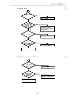
(g)
Peripheral unit problem
CPU error code, fuse,
peripheral units
Fatal CPU error, peripheral unit problem,
peripheral unit setting error, cable problem,
broken fuse
(h)
Verify the system operation
Correct or replace the faulty area
(Verify according to the item
corresponding to the problem.)
Operation
Summary of Contents for HIDIC MICRO-EH
Page 1: ...HITACHI PROGRAMMABLE CONTROLLER APPLICATION MANUAL NJI 350B X ...
Page 12: ...MEMO ...
Page 14: ...Chapter 1 Features 1 2 MEMO ...
Page 50: ...Chapter 4 Product lineup and wiring 4 18 MEMO ...
Page 196: ...Chapter 5 Instruction Specifications 5 146 ...
Page 263: ...Chapter 11 Communication Specifications 11 10 MEMO ...


