Chapter 15 Daily and Periodic Inspection
15-2
(4)
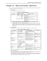
Life of the battery
•
The battery life time is shown below.
Battery life time (total power off time) [Hr] *
Guaranteed value (Min.) @55
°
C
Actual value (Max.) @25
°
C
9,000
18,000
* Battery life time has been changed since Oct. 2002 production (MFG NO.02Jxx) due to hardware modification.
•
The battery life can be determined by checking for the flashing of the OK lamp.
•
The battery life time flag is in the bit special internal output “R7D9.”
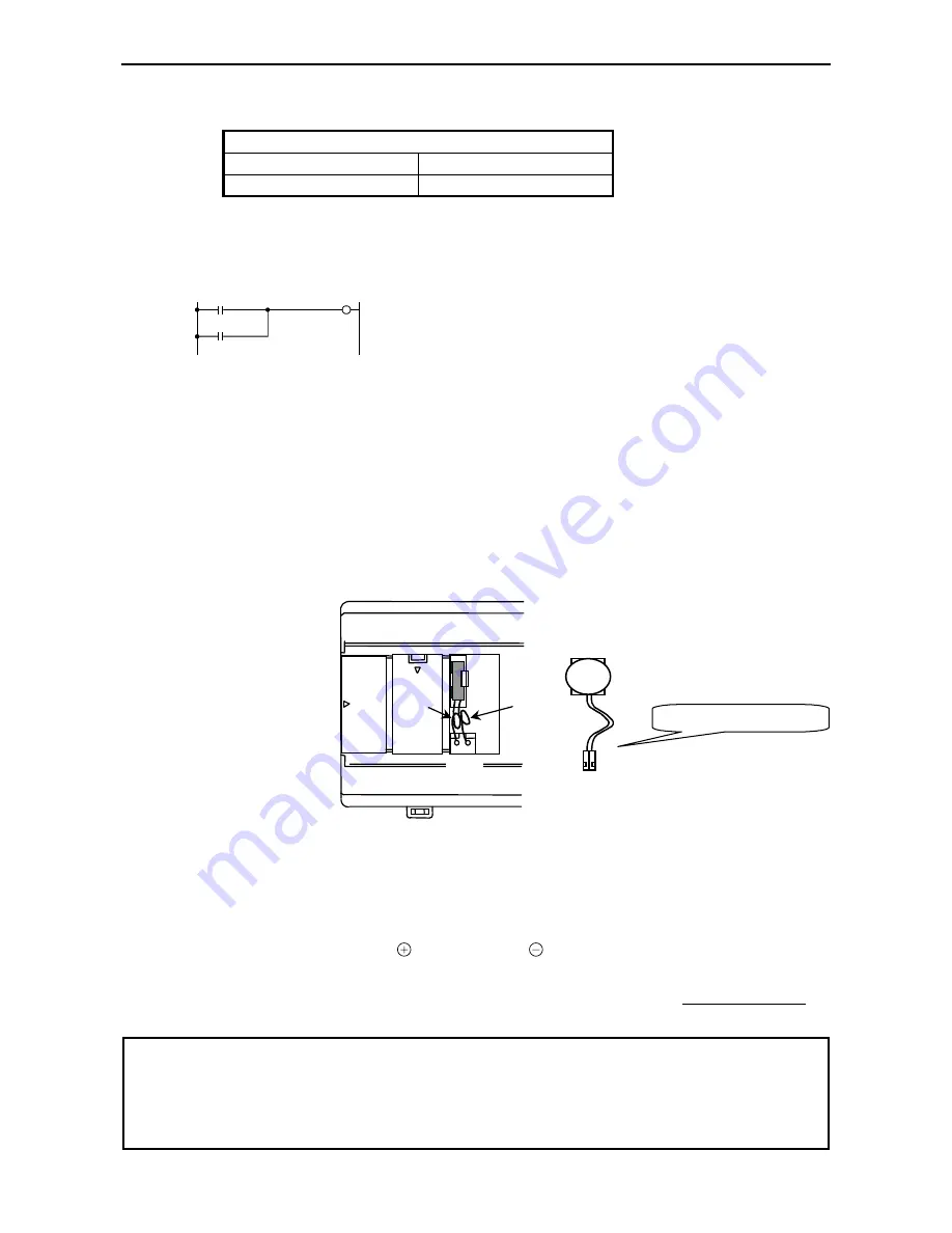
An example of a circuit using “R7D9” is shown below.
R7D9
Y00100
Y00100
The battery error can be output to external output Y00100 by using
the ladder shown to the left.
* R7EE is a bit to enable battery error detection. Be sure to set R7EE
if battery is used.
Figure 15.1 Battery error detection circuit
•
The self-diagnostic error code “71” indicates that the battery is not loaded or that it has reached its life.
•
Exchange the battery every two years even if it is still functional.
•
Use the battery within one year after purchase.
(5)
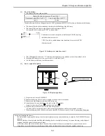
How to replace the battery
Red
Blue
- +
Figure 15.2 Replacing battery
1] Prepare a new battery (EH-MBAT).
2] Replace the battery while the power supply to the basic base is turned on.
3] Remove the old lithium battery from the battery case.
4] Insert the new battery and connect the cable to the CPU module.
Insert it so that the red lead is , and the black lead is .
5] Fold the excess lead and store it in the lead storage space.
(If excess lead is not stored properly, the wire may get caught on the front cover and be severed.)
* When exchanging while the basic unit power turned off, perform steps 4], 5] and 6], in less than 30 minute.
Caution on handling the battery
Be careful when replacing the battery, since incorrect replacement may cause the battery to explode. Use EH-MBAT for new
batteries.
Batteries that have been replaced should be individually placed in a suitable plastic bag (to prevent shorting) and a disposal
company should be requested to dispose of them.
At this time, do not short the batteries, throw them in a fire, dismantle them, exert external force, expose them to water,
charge them or cut the lead wires since doing so leads to the risk that the batteries will ignite, explode or burn up.
Connector on battery side
Summary of Contents for HIDIC MICRO-EH
Page 1: ...HITACHI PROGRAMMABLE CONTROLLER APPLICATION MANUAL NJI 350B X ...
Page 12: ...MEMO ...
Page 14: ...Chapter 1 Features 1 2 MEMO ...
Page 50: ...Chapter 4 Product lineup and wiring 4 18 MEMO ...
Page 196: ...Chapter 5 Instruction Specifications 5 146 ...
Page 263: ...Chapter 11 Communication Specifications 11 10 MEMO ...

