Chapter 5 Instruction Specifications
5-12
R7F
4
R7F
3
R7F
2
R7F
1
R7F
0
Process
time
(
µ
s)
C
la
ssi
fica
tio
n
It
em
num
ber
Ladder symbol
In
str
ucti
on
sy
m
bol Instruction
name
Process descriptions
I/O types used
DER ERR SD
V
C
MICRO-EH
S
teps Remarks
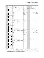
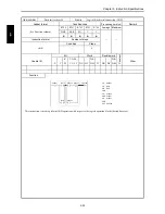
4 FUN 82 (s)
(SLREF (s))
I/O refresh
(any slot)
Refreshes the I/O at the
designated slot.
s: WR, WM
↕
z z z z
311
3
5 FUN 140 (s)
High-speed
counter
operation
control
Performs the starting and
stopping of the count
operation of the specified
counter.
s: WR, WM
↕
z z z z
147
3
FU
N
ins
tru
ctio
ns
6 FUN 141 (s)
High-speed
counter
coincidence
output
control
Performs the enabling and
disabling of the coincidence
output of the specified
counter.
s: WR, WM
↕
z z z z
138
3
7 FUN 142 (s)
High-speed
counter up-
count /
down-count
control
This controls the up-
count/down-count of the
specified counter. (Single-
phase counters only)
s: WR, WM
↕
z z z z
156
3
8 FUN 143 (s)
High-speed
counter
current value
replacement
The counter value of the
specified counter number
will be replaced by the data
stored in the replacement
value storage area.
s: WR, WM
s+1: WR, WM
↕
z z z z
175
3
9 FUN 144 (s)
High-speed
counter
current
value
reading
This function reads the
count value of the specified
counter number and writes
it to the current value
storage range
s: WR, WM
s+1: WR, WM
↕
z z z z
132
3
10 FUN 145 (s)
High-speed
counter
current
value clear
Clears the count value of the
specified counter number.
s: WR, WM
↕
z z z z
157
3
11 FUN 146 (s)
High-speed
counter
preset
The on-preset value and
off-preset value will be set
according to the preset
specifications in respect to
the specified counter
number.
s: WR, WM
s+1: WR, WM
s+2: WR, WM
↕
z z z z
162
3
12 FUN 147 (s)
PWM
operation
control
Starts PWM output of the
specified PWM output
number.
s: WR, WM
↕
z z z z
135
3
13 FUN 148 (s)
PWM
Frequency
on-duty
changes
Sets the frequency value
and the on-duty value of the
PWM output number
specified by the on-duty
value and the specified
frequency value.
s: WR, WM
s+1: WR, WM
s+2: WR, WM
↕
z z z z
173
3
14 FUN 149 (s)
Pulse
output
control
Starts pulse output of the
specified pulse number and
the output is stopped when
the specified number of
pulses are output.
s: WR, WM
↕
z z z z
149
3
15 FUN 150 (s)
Pulse
frequency
output
setting
changes
Pulse output is commenced
at the specified frequency.
Output is stopped when the
number of pulses specified
have been output.
s: WR, WM
s+1: WR, WM
s+2: WR, WM
↕
z z z z
217
3
16 FUN 151 (s)
Pulse output
with
acceleration/
deceleration
Divides the time band and
frequency into 10 levels
and performs
acceleration/deceleration.
s: WR, WM
s+1: WR, WM
s+2: WR, WM
s+3: WR, WM
s+4: WR, WM
↕
z z z z
919
3
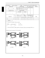
17 FUN 254 (s)
(BOXC (s))
BOX
comment
No processing is performed
in the CPU.
s: WR, WM
z z z z z
—
3
18 FUN 255 (s)
(MEMC (s))
Memo
comment
No processing is performed
in the CPU.
z z z z z
—
3
Summary of Contents for HIDIC MICRO-EH
Page 1: ...HITACHI PROGRAMMABLE CONTROLLER APPLICATION MANUAL NJI 350B X ...
Page 12: ...MEMO ...
Page 14: ...Chapter 1 Features 1 2 MEMO ...
Page 50: ...Chapter 4 Product lineup and wiring 4 18 MEMO ...
Page 196: ...Chapter 5 Instruction Specifications 5 146 ...
Page 263: ...Chapter 11 Communication Specifications 11 10 MEMO ...

