Chapter 5 Instruction Specifications
5-21
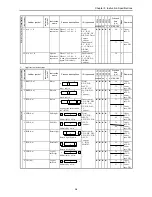
Item number
Basic instructions-11, 12
Name
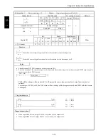
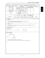
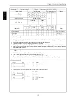
Set/reset coil output (SET, RES)
Ladder format
Condition code
Processing time (
µ
s)
Remark
R7F4
R7F3
R7F2
R7F1
R7F0
Average Maximum
DER
ERR
SD
V
C
Upper case: SET
n
SET
n
RES
S
R
n
SET
n
RES
z
z
z
z
z
0.9
←
Lower case: RES
Instruction format
Number of steps
SET n
Condition
Steps
RES n
1
0.9
←
Bit
Word
Double word
Usable I/O
X
Y
R,
M
TD, SS,
CU, CT
WX WY
WR,
WM TC DX DY
DR,
DM
C
o
nstant
Other
n
I/O number
{
{
Function
n
SET
SET n
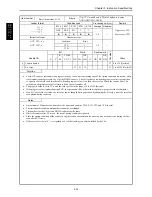
Switches on the device when the operation result obtained up to that point is “1.”
The device that is switched on will not be switched off even if the operation result is “0.”
n
RES
RES n
Switches off the device when the operation result obtained up to that point is “1.”
( ) indicates the display when the Ladder Editor is used.
Notes
•
When a set/reset coil is used on a multi-layer coil, it must be set to the highest level or an arbitrary contact must be entered
immediately before the use.
Example of OK
Example of NG
SET
SET
SET
SET
SET
Program example
X00000
X00001
R100
R100
LD
SET
LD
RES
X00000
R100
X00001
R100
SET
RES
Program description
•
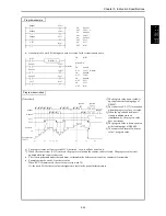
When input X00000 turns on, output R100 turns on. Even if X00000 turns off, R100 remains on.
•
When input X00001 turns on, output R100 turns off.
•
When input X00000 and X00001 both turn on, the one executed later than the other during programming takes a higher
priority.
S
E
T
n
R
ES
n
Summary of Contents for HIDIC MICRO-EH
Page 1: ...HITACHI PROGRAMMABLE CONTROLLER APPLICATION MANUAL NJI 350B X ...
Page 12: ...MEMO ...
Page 14: ...Chapter 1 Features 1 2 MEMO ...
Page 50: ...Chapter 4 Product lineup and wiring 4 18 MEMO ...
Page 196: ...Chapter 5 Instruction Specifications 5 146 ...
Page 263: ...Chapter 11 Communication Specifications 11 10 MEMO ...


