Chapter 5 Instruction Specifications
5-26
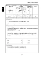
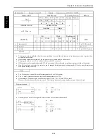
Item number
Basic instructions-20
Name
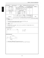
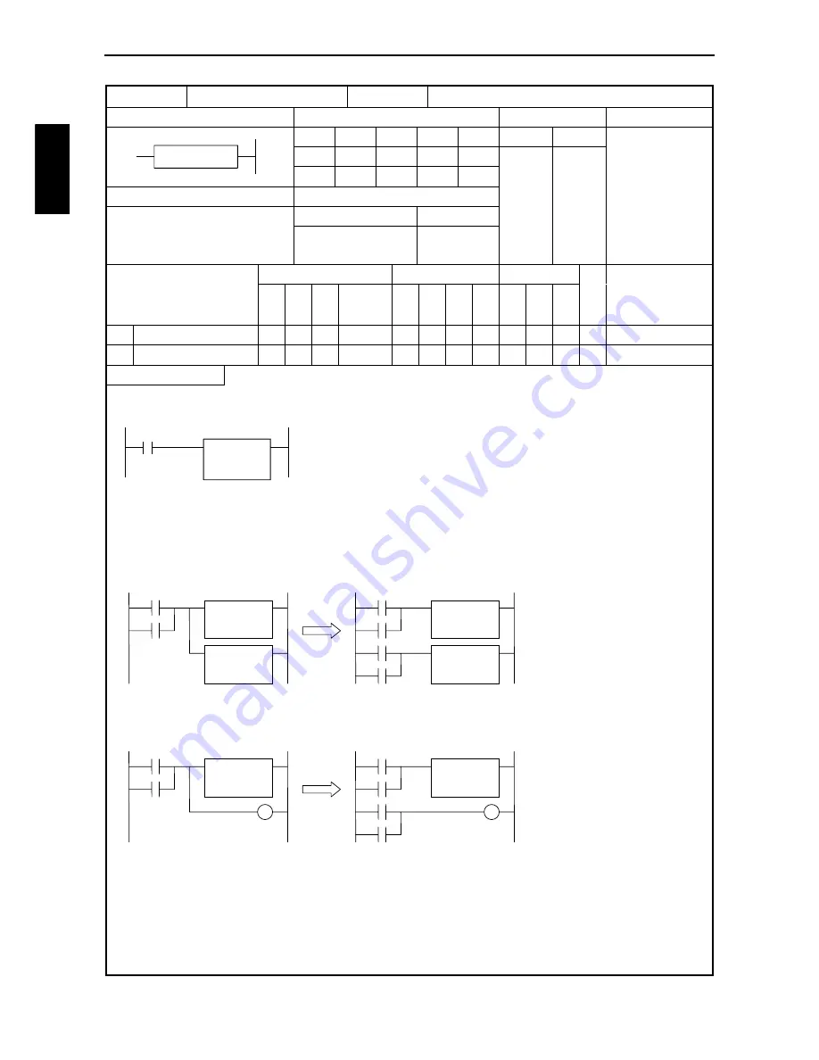
Processing box start and end (PROCESSING BOX)
Ladder format
Condition code
Processing time (
µ
s)
Remark
R7F4
R7F3
R7F2
R7F1
R7F0
Average
Maximum
DER
ERR
SD
V
C
z
z
z
z
z
Instruction format
Number of steps
0.6
Condition
Steps
[ ]
—
3
Bit
Word
Double word
Usable I/O
X
Y
R,
M
TD, SS,
CU, CT
WX WY
WR,
WM TC DX DY
DR,
DM
C
o
nstant
Other
Function
•
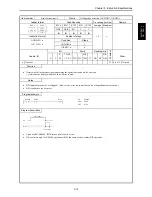
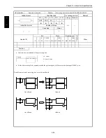
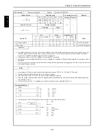
Indicates the start and end of the processing box.
X00001
WY0010=WX0000
LD X00001
[
WY0010=WX0000
]
•
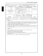
In the above example, the operation inside the processing box will be executed when input X00001 is on.
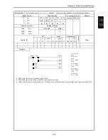
Parallel connection of processing box or coil is not allowed.
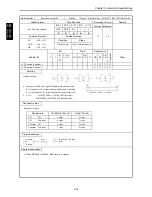
[
]
Not allowed
Allowed
Not allowed
Allowed
Summary of Contents for HIDIC MICRO-EH
Page 1: ...HITACHI PROGRAMMABLE CONTROLLER APPLICATION MANUAL NJI 350B X ...
Page 12: ...MEMO ...
Page 14: ...Chapter 1 Features 1 2 MEMO ...
Page 50: ...Chapter 4 Product lineup and wiring 4 18 MEMO ...
Page 196: ...Chapter 5 Instruction Specifications 5 146 ...
Page 263: ...Chapter 11 Communication Specifications 11 10 MEMO ...

