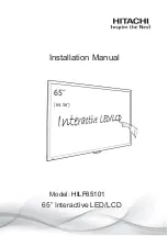
background image


Installation Manual


65

 Interactive LED/LCD


Model: 

HILF65101 

65

˝


(64.56

˝

)


Summary of Contents for HILF65101

Page 1: ...Installation Manual 65 Interactive LED LCD Model HILF65101 65 64 56 ...

Page 2: ... power plug from the socket immediately Failure to do above it may result in an electric shock Contact your dealer for inspection If the monitor has been turned on but there isn t a picture remove the power plug from the socket immediately Failure to do above it may result in an electric shock Contact your dealer for inspection If water is spilled or objects are dropped inside the monitor remove t...

Page 3: ...ulting in overheating or electric shock Don t install in a high humidity environment This may cause overheating or electric shock Don t install near any heat sources such as radiators hot air outlets stoves or other apparatus that produce heat This may cause an electric shock Don t overload sockets or cables beyond electrical capacity Don t use extension leads otherwise this may cause an electric ...

Page 4: ...r cord and AV cables When moving the monitor make sure you remove the plug and cables from the socket or source When unpacking or carrying the monitor at least 4 people are needed Make sure the monitor is carried upright Transport the monitor upright Avoid placing the monitor face up or face down Handle the monitor gently Do not drop Wall mounting safety notes Please make sure the bracket is fixed...

Page 5: ...ving the top cushions 4 Remove the top cushion and take the accessories box out 5 Take vinyl bag off and assembled bracket if it needs Contents of the Accessories box 1 Power cord 2 Remote controller 1 button cell battery included 3 USB cable 4 HDMI cable 5 Pen 6 CD Item Q ty 1 Interactive monitor 1 2 Carton 1 3 Bottom cushion 2 4 Top cushion 2 5 Packing bag 1 6 Accessories box 1 ...

Page 6: ... ⓒ ⓓ ⓔ ⓕ ⓖ ⓗ ⓘ ⓙ ⓚ ⓐ USB for Touch Option ⓑ USB for Touch ⓒ RS232C ⓓ HDMI 1 Input ⓔ HDMI 2 Input ⓕ DISPLAY PORT Input ⓖ PC RGB Input ⓗ PC AUDIO Input ⓘ AUDIO LINE Out ⓙ SPEAKER Out R 10W 8 Ohm ⓚ SPEAKER Out L 10W 8 Ohm ...

Page 7: ...nd existing cover first and screw up again after mounting OPS PC in the slot Power ON OFF Menu Display the main screen menu Source Display Port HDMI1 HDMI2 HDMI3 HDMI Front HDMI OPS PC USB Vol Volume Up Right Vol Volume Down Left Move Up Move Down ⓐ ⓑ ⓒ ⓐ LAN ⓑ Power Switch ON OFF ⓑ AC IN 100V 240V 50 60Hz ...

Page 8: ...vigates upper menu in main OSD menu Navigates input source Navigates down menu in main OSD menu Navigates input source Navigates next menu in main OSD menu Navigates before menu in main OSD menu OK Select the highlighted menu option MENU Activates main OSD menu EXIT Escapes main OSD menu FREEZE Allows you to capture and freeze an image from a moving image that you are watching VOL Volume UP VOL Vo...

Page 9: ...ent resolution is used Please find calibration instructions below for the different operating systems Installation 1 Connect the signal cable to the monitor and then turn on the monitor 2 Connect one side of the USB cable type B USB connector on the monitor side See chapter 3 Signal Source Input for exact location 3 Connect the other side of the USB cable type A USB connector to the computer 4 Tur...

Page 10: ...ion 8 The front B type USB is for laptop touch An USB is automatically connected when you connect a laptop The rear B type USB is for PC An USB is automatically connected to laptop when you connect a laptop and PC at the same time Remove the laptop USB if you want to use a PC 6 Wall Mounting VESA mount size 600 W x 400 H mm Separate wall mount screw and pipe from Monitor As shown below wall mount ...

Page 11: ... power plug is installed correctly at both ends Make sure the signal cable is installed correctly at both ends Check that source equipment is operating correctly Check if the input signal is compatible with this display The image is not centered Check if the input signal is compatible with this display The image is not locked correctly Check if the input signal is compatible with this display If t...

Page 12: ...Rev 001 ...

Reviews: