36
7.4.1. Air Receiver
When your plant airline has the volume of more
than 40 liters, you can operate the
A
with-
out an air receiver tank. In order to prevent the
plant airline pressure from fluctuating or to effec-
tively control the
A
capacity for saving the
power, however, install an external air receiver
tank of the minimum capacity such as:
7. INSTRUCTIONS FOR INSTALLATION [Instructions When Piping]
7.4 Instructions When Piping
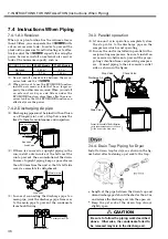
7.4.3 Parallel operation
(1) At one-unit is in operation, completely close
the stop valve to the discharge pipe on the
compressor which is not operating.
(2) In case the unit is installed in parallel with a
reciprocating compressor, be sure to install an
air receiver in-between to prevent the propa-
gating vibration from reciprocating compres-
sor. Connect piping to the air receiver’s outlet
side as shown in the figure.
(1) Do not install a check valve between the air re-
ceiver tank and the
A
.
(2) When you want to use the ECOMODE function,
install an air receiver tank that has a larger ca-
pacity than otherwise required. When you install
an external air dryer and filters under the
ECOMODE function, place them after the air re-
ceiver tank so that the ECOMODE function can
effectively save the power.
ECOMODE Function
22 kW Models
37 kW Models
Not used
0.43 m
3
0.7 m
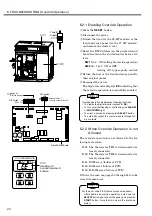
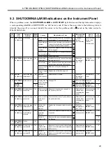
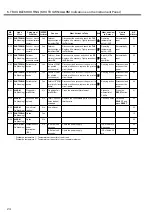
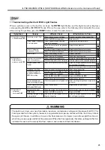
3
Used
0.7 m
3
1.24 m
3
7.4.2. Discharging Air pipe
(1) Discharging pipes must be joined with an Union
or a Flanged joint, and a Stop Valve must be
fixed to them for maintenance and inspection.
(2) If there is concaved or upright piping in the
run, install a drain valve at the bottom of the
run to prevent the accumulation of the drain.
In case of upright piping, keep a space of more
than 500 mm from the unit so that its left side
cover is accessible for detachment.
(3) In case of connecting the discharge pipe to a
main pipe, joint the discharge pipe from over
to the main pipe to prevent the condensate
from back-flowing.
7.4.4. Drain Trap Piping for Dryer
Install a drain trap for dryer as shown in the fig-
ure below after fastening a pet cock to the trap.
●
Length of the pipe between the drain trap and
drain discharge port should be shorter than 3 m,
and release the discharge air into the open air.
●
Keep the pet cock of the drain trap always
slightly open.
Union joint or Flanged joint
Discharging Air
Stop Valve
Drain Valve
Drain Valve
500mm or more
Stop Valve
Discharge Air
Check Valve
Drain Valve
Connect to the outlet of the Air-Receiver
( )
with taper between about 1/100 and
1/200 down to the drain valve.
CAUTION
Be sure to follow the piping work described
above. Otherwise, the condensate failed to
be released may mix in the discharge air.
From Compressor
Discharge Main Pipe

