37
7.5. Compressor Room Ventilation
OSP-22SA(R)
I
OSP-22MA(R)
I
MJ/h
m
3
/min
°
C
Pa
m
3
/min
m
3
/min
m
3
/min
83.7(97.1) 142.3(163.7)
55
75
Ambient temp.+25 Ambient temp.+35
20
20
222(260)
378(440)
70(108)
92(154)
(38)
(62)
Ventilation data
Model
Item
7. INSTRUCTIONS FOR INSTALLATION [Compressor Room Ventilation]
(1) The air-cooled type compressor will release in-
ternal heat discharged as hot exhaust wind.
Be careful for ventilation of the room. The
table at the right shows discharged heat from
the compressor. By calculating assumed ven-
tilation capacity with the room, when the am-
bient temperature seems to exceed 40
°
C., the
forced ventilation should be equipped to the
room.
(2) Air intake hole must have an opening of larger
than 1 square meter per each compressor to
the place as low as possible in the room. Air
intake port must face to the place where fine
dust or other harmful material in the ambient
air are not taken into the unit.
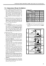
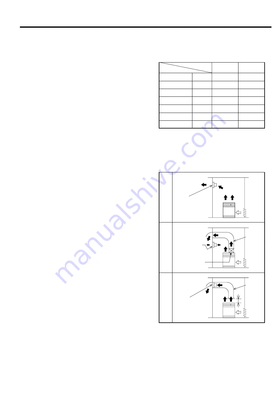
(3) Total ventilation
As the
figure A
, ventilation fan capacity in
case of ventilating the room in whole where
the compressor is installed, greater capacity
than the recommended
ventilation fan capac-
ity
q
on the right table is required. (How-
ever, it is under the condition that the allow-
able temperature rise in the house is 5
°
C.)
Place the ventilation fan on top of the room.
(4) Discharge air duct
●
Based on the air exhaust capacity of the com-
pressor shown in the right table, calculate the
resistance of the air exhaust duct. If it is kept
within 20 Pa, no need for an extra ventilation
fan. In such case, connect the duct directly to
the exhaust air port of the compressor as
shown in the
figure B
.
The discharge air duct should be detachable
structure, so that it will not hinder mainte-
nance accessibility.
On the other hand, to ventilate the exhaust
air from the dryer, install a fan with larger
ventilation fan capacity than the recom-
mended one
e
to the house.
●
In case where pressure loss of the duct is
greater than 20 Pa, on consideration of such
pressure loss, a ventilation fan with the ca-
pacity larger than the recommended quantity
w
on the right table should be installed inside
the duct. According to the discharged air tem-
perature rise in the right table, choose an ap-
propriate ventilation fan.
In this case, do not connect the duct directly to
the exhaust air port of the compressor, but in-
stall a hood at the entrance of the duct, and
keep distance h (h must be larger than the
duct diameter) between the duct and the port.
(Figure C)
●
Do not release the exhaust air from the dryer
through the duct equipped with a ventilation
fan. Forced ventilation may cause internal
freezing to dryer’s air cooler.
Heat generation
Air exhaust capacity of
compressor
Discharged air
temperature
Outside allowable
pressure loss
Recommended ventilation
fan capacity
q
Recommended ventilation
fan capacity
w
Recommended ventilation
fan capacity
e
Figure
A
Figure
B
Figure
C
OSP-37SA(R)
I
OSP-37MA(R)
I
NOTES:
(1) The values in the parentheses are for the models with a built-
in air dryer.
(2) The values of the
e
are for the models with a built-in air dryer
where the duct’s end contacts directly onto the
A
(Figure B).
h
Air exhausted
from
air dryer
Air exhausted
from air dryer
Air exhausted
from air dryer
Air
exhaust
duct
Air
exhaust
duct
This part must
be detachable.
Air
intake
hole
Air
intake
hole
Air
intake
hole
Air exhaust
Air exhaust
Air exhaust
Ventilation fan
Refer to recommended
ventilation fan capacity
q
on the table above.
Ventilation fan
Refer to recommended
ventilation fan capacity
e
on the table above.
Ventilation fan
Refer to recommended
ventilation fan capacity
w
on the table above.

