background image

61

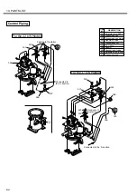
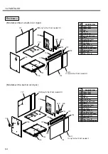
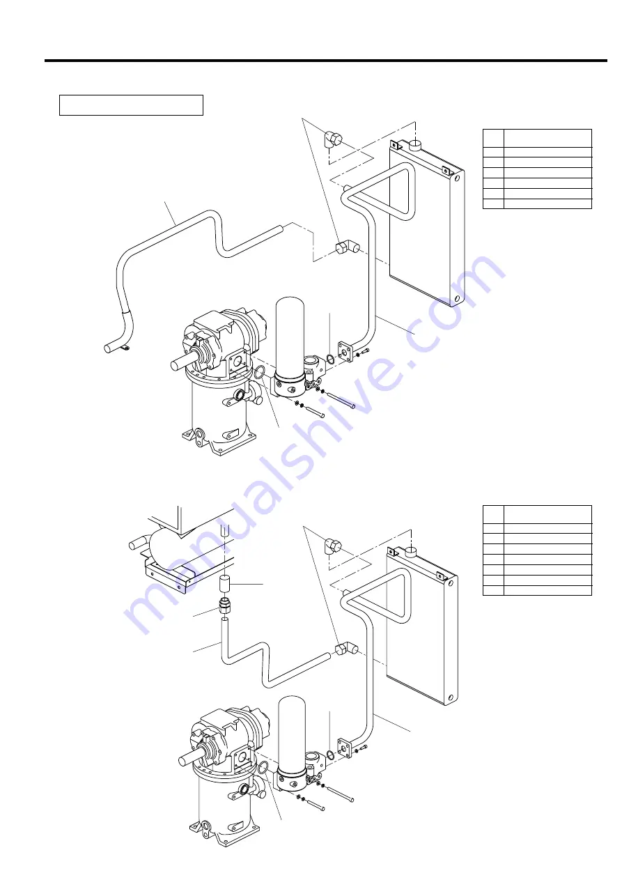
10. PARTS LIST

551
561
663
666
667
687

O-ring
Discharge Pipe (2)
Discharge Pipe (1)
Joint, straight
Joint, elbow
O-ring

Discharge Air Piping

ITEM

NO.

DESCRIPTION

[Models without a built-in air dryer]

[Models with a built-in air dryer]

551
561
663
666
667
687
863

O-ring
Discharge Pipe (2)
Discharge Pipe (1)
Joint, straight
Joint, elbow
O-ring
Socket

ITEM

NO.

DESCRIPTION

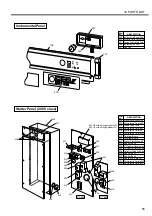
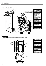
667(22kW)
666(37kW)

663

551

687

561

666

863

667(22kW)
666(37kW)

663

551

687

561

Summary of Contents for HISCREW 2000 Series

Page 1: ...on This means convenient information to know This shows reference page number This shows the information specific to the models with a built in air dryer IMPORTANT CAUTION HITACHI ROTARY SCREW COMPRESSOR Air Cooled Type Before you start operating be sure to read this manual carefully in order to operate the machine safely and properly Also prepare the manual near the machine to make it available a...

Page 2: ...ck cover of the manual International System of Units SI For the unit of pressure the International System of Units SI is used throughout this manual To convert it into the conventional system of units use the following conversion formula 7 kgf cm2 0 69 MPa or 1 kgf cm2 0 098 MPa Description of Type Never remove a protective device from the air compressor or modify the air compressor Never fail to ...

Page 3: ...stem 33 7 INSTRUCTIONS FOR INSTALLATION 34 7 1 Verification of Components 34 7 2 Instructions When Conveying 34 7 3 Instructions When Installing 35 7 4 Instructions When Piping 36 7 5 Compressor Room Ventilation 37 7 6 Instructions on Electrical Wiring 38 8 PERIODIC MAINTENANCE 44 8 1 Periodic Maintenance for Compressor 44 8 2 Maintenance Standards A 45 8 3 Maintenance Standards B 46 8 4 Auto Drai...

Page 4: ...mpressor is operating or immediately after you have stopped it that is the system is still internally pressurized Otherwise the hot pressurized air and or oil may gush out and eventually you may be burnt or injured Carefully read the Instruction Manual before checking or replacing the oil separator Replace the oil separator element and housing whenever the housing is scratched deformed or corroded...

Page 5: ...ne syn thetic oil Replace the oil and the oil separator element and housing regularly as scheduled by the Instruction Manual Failure to observe these may deteriorate the oil and eventually cause a fire and or explosion ROTATING PARTS Keep your hands and any objects away from the rotating parts pulleys belts cooling fans etc Be careful on the stopped air compressor in an automatic stop restart cont...

Page 6: ...ty specification voltage and frequency Discharge Air Outlet left hand side Compressed air outlet A nameplate is attached on the right enclosure panel It indicates the A type model number motor out put and frequency working pressure and manufacturing number Inform the Hitachi distributor of such information whenever asking it to service your A IMPORTANT Cooling Air Outlet from air dryer To discharg...

Page 7: ...in the air from being taken in the com pressor Relief Valve This unlocks and re leases compressed air when the inner pressure of the separator abnor mally increases Oil Level Gauge Oil Temperature Control Valve This retains the oil tem perature at the appropri ate level Suction Throttle Valve This controls capacity of air intake against load fluctuation Driving Unit This increases the revo lution ...

Page 8: ...codes The ALARM and SHUTDOWN lights indicate that a problem has happened AUTO START Light green For the M type A with A mode capacity control p 29 Becomes on non flashing when in an automatic stop state and on flashing when in an automatic restart state It also becomes on flashing when the instantaneously interrupted power is recovered For the models with a built in air dryer Flashes for 3 minutes...

Page 9: ...ton and Light yellow Press the ECOMODE button to enable an ECOMODE function that temporarily reduces the cutout pressures The ECOMODE light becomes on non flashing and flashing when this function is respectively enabled and activated 3 HOW TO OPERATE Air Compressor Instrumentation Buttons Lights for Control Buttons Lights for Shutdown and Alarm Indication 1 If you want to permanently enable a remo...

Page 10: ... screen displays C together with the discharge air temperature e Press the SELECT button The screen displays L together with the loading rate The system flushes figures when in calculation r Press the SELECT button The screen displays U together with the total loading time 10 000 Refer to the IMPORTANT t Press the SELECT button When the alarm shutdown light is on flashing the screen displays E fla...

Page 11: ...LECT button to move to the cutin pres sure screen Repeat the above actions w through r to change the cutin pressure setting Press the RE SET button The screen returns to what you have left with the action q above To display the capacity control settings do as follows q Hold down the RESET button and press the SELECT button more than 3 times The screen displays 0 L as an example see the IMPOR TANT ...

Page 12: ...run the machine by way of initial start up Capacity control of S type is preset to I type control and M type is to P type AUTO control Refer to page 12 for the setting of control function when the control type is changed Compressor shifts repeatedly between full load and no load operation within the range of its discharge pres sure between 0 69 MPa and 0 59 MPa Before turn the power ON make sure i...

Page 13: ...ure Make sure that it is stable between 65 C and 100 C y Make sure that 5 to 10 minutes after starting the refrigerant pressure gauge reads 0 41 to 0 73 MPa u Make sure that about 20 minutes after start ing the automatic condensate trap starts drain ing the condensate 3 HOW TO OPERATE Initial Start Up 3 3 3 Operation 3 3 4 Stop q Press the STOP button The compressor stops w Be sure that the pressu...

Page 14: ...s whichever is appropriate 3 Do not set the SW2 No 3 4 to other than the above 3 4 2 How to Set Capacity Control Type to U q Disconnect the power w Remove the starter control box cover e Place the No 4 pin of the DIP switch SW2 in an off position r Return the starter control box cover to its origi nal place t Reconnect the power y Display the capacity control setting screen on the digital monitor ...

Page 15: ...n off position Method 3 On an External Setting Switch q Disconnect the power w Remove the starter control box cover e Connect the wires between the A s starter control box and an external control panel and between the A s starter control box and the external setting switch For information on a wiring diagram see pages 40 through 43 r Make sure that the No 4 pin of the DIP switch SW1 on the printed...

Page 16: ...ng NOTE The shaded cells indicate a standard factory setting This page describes for the models with a built in air dryer No 1 OFF OFF ON ON No 2 OFF ON OFF ON Independent Automatic Manual DRYER Light OFF Without Built in Air Dryer With Built in Air Dryer DIP Switch SW2 Air Dryer Operation Mode by connecting disconnect ing the power by START and STOP buttons by DRYER button ON non flashing for nor...

Page 17: ...o the motor and may damage some parts or even cause SHUTDOWN of the compressor Investigate the cause and take necessary measures when the Relief Valve functions or the compres sor stops by other safety device Ask your dealer or your nearest Hitachi Service Station if there is any question When the A automatically stops and restarts frequently or the ambient temperature and humidity are high open t...

Page 18: ... OIL 2000 r Digital monitor displays run hour in 10 hours as a unit Press the SELECT button on the instrument panel and check if the discharge temperature is within the range between 65 C and 100 C After temperature stabled t Make sure that 5 to 10 minutes after starting the refrigerant pressure gauge reads 0 41 to 0 73 MPa y Make sure that about 20 minutes after start ing the automatic condensate...

Page 19: ...draining valve r Open the oil draining valve t The oil comes out and the condensate follows y When the oil starts to come out again close and plug the oil draining valve If the condensate is not discriminable from the lubricant check its viscosity by your finger tips while draining Be sure the condensate is well cooled before touching it If the condensate sticks to your fingers the lubricant is co...

Page 20: ...the power and replenish some more of lubricant Ask your dealer or Hitachi s service station for replace ment of the genuine synthetic oil NEW A OIL 2000 4 liters oil can Part No 330 20 liters oil can Part No 332 The genuine synthetic oil may get darkened due to its chemical additives soon after start of use but it is not abnormal CAUTION Replenish the oil genuine synthetic oil periodically to main...

Page 21: ...cause some of it is circulating in pipes or oil cooler 2 Confirm that the pressure decreases to the level of the ambient air pressure Then turn the POWER OFF and replenish some more lubricant into the replenish port 3 After replenishment fasten the plug on the re plenish port securely 4 Press the START button again to check the oil level when the compressor is at its full load Discharge Check and ...

Page 22: ...tor displays the discharge air temperature e Remove the causes of alarm Refer to pages 23 through 24 SHUTDOWN ALARM Indications on the Instrument Panel for countermeasures 5 1 2 SHUTDOWN Light Flashing The A stops operating q Shutdown happens Ex Temperature sensor de tects excessive in the discharge temperature of the compressor w The SHUTDOWN light flashes The digital monitor displays the dischar...

Page 23: ...r loose wires connectors Sometimes this may solve the problem If the problem persists or the shutdown code is still displayed proceed to enable an over ride operation 3 When such time is longer than 5 seconds the sensor detects it as a power failure and stops the unit In such case the unit will not restart automatically So press the START button to start the unit again 1 Power supply interruption ...

Page 24: ...e override operation is not allowed to the fol lowing error codes E 31 The thermistor TH1 is disconnected or loosely connected E 32 The thermistor TH2 is disconnected or loosely connected E 41 ROM error failure of PCB E 42 RAM error failure of PCB E 43 E2ROM error failure of PCB If this is the case see pages 23 through 24 to take corrective measures For the error code E 33 failure of pressure sens...

Page 25: ... Correct it if required Check and correct the capacity control settings and or readjust the modulator valve if the discharge pres sure is higher than the specification pressure Check the oil separator element Replace it if it is clogged Check the motor for insulation resistance etc Check the air end Ventilate the room to reduce the ambient temperature to 40 C Add oil Disconnect the power and make ...

Page 26: ...connect the TH1 wires Disconnect the power and check the TH2 Replace it if necessary Tightly reconnect the TH2 wires Disconnect the power and check the PS Replace it if necessary Tightly reconnect the PS wires Disconnect and reconnect the power If a problem still occurs replace the printed circuit board Disconnect and reconnect the power If a problem still occurs replace the printed circuit board ...

Page 27: ...the refrigerant compressor Replace the 49FC Tightly reconnect the wires Reduce the ambient temperature to below 40 C Clean the condenser and or replace the cooling fan Adjust the hot gas bypass valve to correctly set a refrigerant pressure Replace the hot gas bypass valve if it is not adjustable Clean the condenser fins Replace the PS2 Replace the 49FC Replace the IM4 and or IM5 Replace the contac...

Page 28: ...ssure Gauge Indication fault Leak in Pipes Intake Filter clogging Oil Separator clogging Pressure Regulating Valve fault Suction Throttle Valve fault Mechanical Sealing damage Pressure Gauge Indication fault Excess Over Rated Pressure Relief Valve Incorrectly adjusted or failed Poor operation of Oil Temperature Control Valve Suction Air Temperature too high Oil Scavenge Pipe System clogging Oil Se...

Page 29: ...18 through 19 2 Do not operate the unit without protective equipment In case of SHUTDOWN read this section 5 TROUBLESHOOTING to remove the cause If the cause is unknown inform and ask your dealer or Hitachi Service Station WARNING Running the unit with its loose belt brings not only lowered discharge air capacity due to its slipping but also life of belt shortened If belt is broken during the oper...

Page 30: ...ompressed Air and Heat Exchanged Lubricant are separated in the Oil Separator into the Compressed Air and the Lubricant Segregated Lubricant is cooled in the Oil Cooler afterwards and returns to the suction side of Compressor then it makes Heat Exchange with another Compressed Air again 63E Pressure switch 63SV Pressure differential sensor of air intake filter Lubricant flow Compressed air flow Co...

Page 31: ... is very often operated unloaded or when the air consumption in termittently fluctuates This is applicable when fluctua tion of discharge pressure must be kept less Type of capacity control Purpose S type M type MPa MPa MPa 0 69 0 83 0 92 0 69 0 83 0 92 0 59 0 74 0 82 Suction throttle valve closed Suction throttle valve open Suction throttle valve closes partly Suction throttle valve closed Suctio...

Page 32: ...trol Mo tor ON OFF Control Type is adopted However the number of stops the motor makes is limited to 3 times during 30 minutes 4 When the I type unloading operation contin ues for 3 minutes the P type capacity control is activated In case of P Type Motor ON OFF Control Type 1 The Motor will not start again for 45 seconds when it stops 2 Install an external air receiver tank If you fail to ob serve...

Page 33: ...e operating temperature and thus minimize the condensate production If higher always the I type capacity control is selected Afterwards the P type capacity control may be selected and when the conditions are sat isfied the motor may be automatically stopped 6 2 5 ECOMODE Function ECOMODE function is a standard feature of the S and M type A It is disabled however by Hitachi before shipping the A 1 ...

Page 34: ...n the compressed air demand causes the U type not the I type to be selected IMPORTANT automatically used with the ECOMODE light flashing The cutoff pressure shifts from stan dard to optional step by step until it reaches the cutin pressure 0 05 MPa or a load un load cycle decreases to below 30 seconds Thus you can save the power as indicated by the shaded areas in the illustration 2 Precautions Wh...

Page 35: ...rigerant is squeezed by the capillary tube H and sent to the air cooler B as a low pressure liquid refrigerant The refrigerant is heat exchanged with compressed air and evaporated It is sucked as overheated steam into the refrigerating compressor D recompressed and then discharged This cycle is repeated The hot gas bypass valve G works automatically depending on a load and an ambient temperature a...

Page 36: ...6AI OSP 22S M5ARI OSP 22S M6ARI OSP 37S M5AI OSP 37S M6AI OSP 37S M5ARI OSP 37S M6ARI Total Weight kg 540 590 760 830 7 INSTRUCTIONS FOR INSTALLATION Machine Nameplate Check Standard Accesstory 7 1 Verification of Components 7 2 Instructions When Conveying Fork Lift Crane Output kW Model Frequency Hz Foundation Bracket Foundation Bolts M12 M16 2 sets Fork Slot Covers 4 pieces M6 Bolts 8 pieces Con...

Page 37: ...a space of 0 5 m or more before setting up a pipe around the unit Foundation If the vibration of the location exceeds 5µm provide the vi bration absorbable mat under the unit Such vibration may reach the compressor and dam age its bearings Maintenance Space Back space Keep a space of 0 5m or more Intake Air and Maintenance Space Right hand side space Keep a space of 0 5 m or more before setting up...

Page 38: ...E Function 22 kW Models 37 kW Models Not used 0 43 m3 0 7 m3 Used 0 7 m3 1 24 m3 7 4 2 Discharging Air pipe 1 Discharging pipes must be joined with an Union or a Flanged joint and a Stop Valve must be fixed to them for maintenance and inspection 2 If there is concaved or upright piping in the run install a drain valve at the bottom of the run to prevent the accumulation of the drain In case of upr...

Page 39: ... nance accessibility On the other hand to ventilate the exhaust air from the dryer install a fan with larger ventilation fan capacity than the recom mended one e to the house In case where pressure loss of the duct is greater than 20 Pa on consideration of such pressure loss a ventilation fan with the ca pacity larger than the recommended quantity w on the right table should be installed inside th...

Page 40: ...ts protective functions and may cause to serious accident like burning the compressor Ask your dealer if you must have a modifica tion to the unit 3 Be sure to turn the POWER OFF to get rid of electric shock accident when the cover of starter should be removed for wiring work or inspection Attach a plate on the POWER side saying Maintenance Work Do Not Electrifying to prevent other workers from re...

Page 41: ... down is prepared at the a normal open contact Rated current is AC200V 3A Use a ground cable of 22 mm2 or more Only pulse signal of 0 5 second or more for Start Stop Signal can actually control the compressor at remote operation If such signal from remote place is a level signal Make Contact following failures can happen 1 The unit automatically starts operation by setting the remote operation swi...

Page 42: ... D This shows setting at dryer side EF1 EF2 EF3 42 O O Y Y R W B R R 7 6 7 Standard voltage wiring diagram 200 220 V 7 INSTRUCTIONS FOR INSTALLATION Instructions on Electrical Wiring Compressor motor Cooling fan motor Main electromagnetic contactor Electromagnetic contactor for Electromagnetic contactor for Electromagnetic contactor for fan Thermal relay Control PC board Display PC board Thermisto...

Page 43: ...er Alarming Prestarting OFF OFF No 1 2 Air Dryer Operation Mode ON OFF ON OFF SW2 OFF OFF OFF OFF No 3 4 Capacity Control Mode ON ON ON OFF NOTE The settings in the parentheses are for the models without a built in air dryer Only for the M Type A W R G G R R This shows the circuit for the models with a built in air dryer ATTENTION 1 Wiring and device shown with short dashes line is option or out o...

Page 44: ...uipped only 37 kW equipped This shows setting at compressor side This shows setting at dryer side O O Y Y R W B R R 7 6 8 Differential voltage wiring diagram 380 400 415 440 V 7 INSTRUCTIONS FOR INSTALLATION Instructions on Electrical Wiring Compressor motor Cooling fan motor Main electromagnetic contactor Electromagnetic contactor for Electromagnetic contactor for Electromagnetic contactor for fa...

Page 45: ...te start External load unload a contact Short Circuit AC200 V AC200 V AC200 V input External Load Unload Remote Operation Dryer Answer Operation Answer Overload Reversal Phase Flat Cable W R G G R R This shows the circuit for the models with a built in air dryer 7 INSTRUCTIONS FOR INSTALLATION Instructions on Electrical Wiring Relay output Symbol Name Performance Y1 Operation relay ON at operation...

Page 46: ...ntenance for Compressor Before Maintenance work read To Use in Safety p 2 again carefully Be sure to turn the POWER OFF when check or maintenance is carried out If not such work may cause serious accident like electric shock When part of the unit needs to be disassembled or removed be sure to release its internal pressure to the level of ambient air pressure Residual high pressure inside the unit ...

Page 47: ...en 0 41 and 0 73 MPa Check by hand Check condensate drainage clean it if required Visual check of wear check abnormal noise Replace the housing and square ring as well 1M ohm or more at DC500 V Mega Terminal refastening electric line cover check and cleaning During cleaning also replace a seal washer Replace the cap seal valve plate and O ring Clean Replace the diaphragm and rubber sheet Clean Cha...

Page 48: ...Check Clean Replace Oil level must be within red lines during operation Must be between 65 C and 100 C Must be between 0 41 and 0 73 MPa Check by hand Check condensate drainage clean it if required Visual check of wear check abnormal noise During cleaning also replace a seal washer Replace the housing and square ring as well 1M ohm or more at DC500 V Mega Terminal refastening electric line cover c...

Page 49: ...wl guard C Turn the latch at about 45 degrees and pull out downward The bowl assembly D and bowl guard C can be removed from the body A together r Remove the screen B from inside the bowl assembly D and wash also wash the bowl at a proper time t Fit the washed screen B on the bowl assem bly D in the original position Install the auto drain trap in the reverse order of disassembly Use home use neut...

Page 50: ...eturns to the former pressure level 8 6 2 In case of U type Control q Adjust the Stop Valve so that the discharge pressure reaches to its specified level w By closing the stop valve gradually and check if the discharge pressure settles within the range specified in the table below e In case where discharge pressure exceeds the range of the table below or if the relief valve actuates adjustment of ...

Page 51: ...in the head as before o Fasten the element by the hand without use of a tool like filter wrench 8 PERIODIC MAINTENANCE Oil Filter Element If a tool like filter wrench or pipe wrench is used to fasten the oil filter element element s housing part may be damaged or deformed and will cause leak or breaking Be sure to fasten it by the hand tightly When the Oil Filter clogged lubricant supply to the co...

Page 52: ...bove cleaning more than 5 times If its contamination is heavy replace it with a new one After cleaning of filter element put a lamp inside the element and check if no damage happens to it before reuse IMPORTANT u Wipe dust or stains off of the air intake filter housing and inside the suction filter cover i Push the filter element in its housing firmly as it was before o Place the side with a mark ...

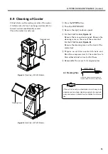
Page 53: ...kW models Figure B Remove the cleaning cover on the front of the cooler duct t Prepare an air blow nozzle with bent end Blow the compressed air to the cooler fins to blow adhered dust or waste off of them y Reassemble the covers to its original place If the unit is heavily contaminated more heavy duty cleaning such as steam cleaning seems to be required Ask your dealer or Hitachi Service Station f...

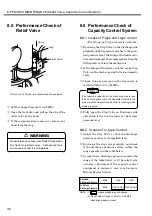
Page 54: ... work CAUTION 8 10 2 Replacement of Minimum Pressure Check Valve q Press the STOP button w Turn the power OFF e Close the stop valve on discharge side r Wait until the pressure in the compressor de creases to the ambient air pressure t Hook a spanner on a hexagonal portion of the minimum pressure check valve body Do not unfasten its lock nut portion remove the body in whole instead y There are a c...

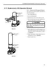
Page 55: ...ressor de creases to the ambient air pressure Figure B Figure A Be careful not to burn your skin because the surface of the housing is very hot just after the stop CAUTION t Hold a special tool around the upper part of the cylinder shaped housing and unfasten the housing by turning it anticlockwise to remove it Figure A y Remove the housing Gently pull up the inter nal element to remove Figure B u...

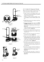
Page 56: ...t set in a ditch on the element head t Reverse the above procedure and set the ele ment into the housing Figure C y Firstly pull only the element down Hold it with both hands and push it down so that the end plate of the element adheres to the head At this time be careful not to allow the gasket slip out from the head Figure D u Hold the housing by both hands and put it on the thread portion of th...

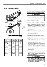
Page 57: ...w Press the plate towards belt span surface of V pulley and M sheave then using a tension meter to measure the pressing load and bend ing displacement at its span center If the bending is kept within the range shown in the left table there is no need for tension adjustment If deviation from the stated val ues is obvious tension adjustment is needed Ask your dealer or Hitachi service station for th...

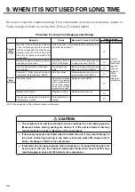
Page 58: ...ain the lubricant More than 1M ohm at DC 500V Mega No rusting in the slots Smooth rotation Replace in whole No deterioration nor rusting NOTE Ask your dealer or Hitachi Service Station for information Criteria Measures If Criteria Is Not Filled 3 to 6 months 6 to 12 months Storage Period Check it for its tension Refer to the mainte nance standards and no crack from appear ance and enough elastic f...

Page 59: ...sor Air End Assembly Male Rotor Female Rotor 50 Roller Bearings 25 Roller Bearings 20 Angular Ball Bearings 40 Angular Ball Bearings Casing D Casing Spacer 50 roller bearing S Cover 40 Mechanical Seal S Cover Packing D Cover D Cover Packing D Casing Packing Knock Pin Key MD Stop Plate FD Stop Plate MD Set Bolt FD Set Bolt 20 Collared Roller Bearing 40 Collared Roller Bearing Snap Ring V Pulley V P...

Page 60: ...lt Adjusting Bolt Plate 2 motor fixing Retainer motor base ITEM NO DESCRIPTION Cooling Fan 156 540 621 622 624 625 650 652 Bell Mouse Cooler Fan Motor Fan Shaft Key Fan Washer Set Bolt Air Exhaust Duct Impeller ITEM NO DESCRIPTION 10 PARTS LIST Motor Pulley 101 120 109 106 122 134 121 108 128 144 130 161 140 132 For the 37 kW Models For the 22 kW Models 621 622 650 652 625 624 156 540 625 624 156 ...

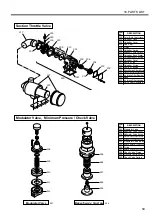
Page 61: ... Seat Assembly 507 508 509 510 511 512 552 556 557 558 864 865 Modulator Valve Modulator Valve Cover Modulator Valve Spring Modulator Valve Diaphragm Assembly Modulator Valve Rubber Packing Modulator Valve Body Minimum Pressure Check Valve O ring Minimum Pressure Valve Piston Check Valve Piston Pressure Control Spring Check Valve Spring 10 PARTS LIST ITEM NO DESCRIPTION ITEM NO DESCRIPTION Modulat...

Page 62: ...enish Port O ring Replenish Port Plug Thermister Oil Level Gauge Assembly Lubricant NEW A OIL 2000 4 liters Lubricant NEW A OIL 2000 20 liters Special tools for oil separator Oil Level Gauge Single Packing oil case Nipple oil filter Skirt Packing skirt Element head Oil Temperature Control Valve O ring oil temperature control valve Cover oil temperature control valve O ring Option 10 PARTS LIST ITE...

Page 63: ... Discharge Air Piping ITEM NO DESCRIPTION Models without a built in air dryer Models with a built in air dryer 551 561 663 666 667 687 863 O ring Discharge Pipe 2 Discharge Pipe 1 Joint straight Joint elbow O ring Socket ITEM NO DESCRIPTION 667 22kW 666 37kW 663 551 687 561 666 863 667 22kW 666 37kW 663 551 687 561 ...

Page 64: ...lve Pressure sensor 3 5 Orifice Adaptor Vacuum relief valve Solenoid Valve 20US Pressure switch Control Piping ITEM NO DESCRIPTION For the 22 kW Models For the 37 kW Models Fixed onto the starter Fixed onto the starter Connected to the A section A 672 533 566 588 507 506 505 501 589 507 671 672 533 Connected to the A section ...

Page 65: ...t Base cooling fan motor Air Exhaust Duct Assembly Air Intake Duct air dryer Cooler Duct 1 Cooler Duct 2 Cooler Duct 3 Inspection Cover Motor Duct Air Intake Duct 1 Air Intake Duct 2 Air Intake Duct 3 Front Cover air dryer Support air dryer Support Plate air dryer ITEM NO DESCRIPTION Models without a built in air dryer Models with a built in air dryer For the 22 kW Models For the 37 kW Models Fixe...

Page 66: ...t in air dryer 419 435 701 702 704 706 707 708 711 713 717 718 720 721 737 752 796 Rubber Bush Rubber Bush Door Magnet Front Cover Instrumental Panel Chain Right Side Cover Power Cover Top Cover Rear Cover 1 Left Side Cover Noise Proofing Plate Common Base Side Cap Rear Cover 2 Cover discharge pipe ITEM NO DESCRIPTION 717 718 720 721 707 737 706 701 704 only for the 37 kW models 702 737 711 435 41...

Page 67: ... 42 Electromagnetic Contactor 6 Electromagnetic Contactor 88F Terminal Board Terminal Board Copper Plate Assembly Rubber Bush CPU Printed Circuit Board for S type CPU Printed Circuit Board for M type Printed Circuit Board Transformer Rubber Bush Rubber Bush Cooling Fan starter Electromagnetic Contactor 52C Electromagnetic Contactor 88 Starter Panel 200 V class ITEM NO DESCRIPTION 427 737 423 706 4...

Page 68: ...magnetic Contactor 52C Electromagnetic Contactor 88 Starter Panel 400 V class ITEM NO DESCRIPTION 900 901 902 903 904 905 907 908 915 919 920 945 950 951 958 959 Dryer Assembly Compressor Heat Exchanger Condenser Condenser Fan Condenser Fan Motor Fan Control Switch High Pressure Switch Refrigerant Pressure Gauge Thermostat OHR Hot Gas Bypass Valve Stop Valve Condensate Trap Assembly O Ring condens...

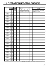
Page 69: ...r Remarks Parts Replacement Other matters and To be Recorded Discharge Pressure MPa Suction Air Temperature C Refrigerant Pressure MPa Discharge Temperature C Control Range 0 to 40 5 to 40 Control Range 0 41 to 0 73 Control Range 100 or below NOTE The values in the brackets are for the models with a built in air dryer ...

Page 70: ...68 This page is intentionally blank ...

Page 71: ...ion throttle type I type vacuum type U type suction throttle type I type vacuum type P type auto start stop 10 1 1 MPa m3 min kW kW liter S type M type kW W kg mm 0 83 0 92 0 69 0 92 0 69 0 83 3 1 2 9 3 8 5 0 6 3 5 3 760 830 1 400 970 1 400 540 590 1 200 890 1 260 25 2 25 1 13 8 37 22 Item Unit OSP 22S5A R I S6A R I OSP 22M5A R I M6A R I OSP 37S5A R I S6A R I OSP 37M5A R I M6A R I NOTE 1 means sta...

Page 72: ...an S HIA 542 2002 1 Model Compressor Serial No Installed on Start Up on Purchased from OSP kW Hz day month year day month year Phone Sales Person Note down your Compressor s Specifications for reference in the future ...

Reviews: