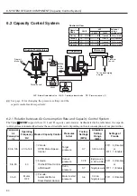
PID stands for Proportional, Integral, and Differential.
CPCS stands for Constant Pressure Control System.
HI
SCREW
Motor
Pressure Sensor
CPCS Motor Speed Control by Inverter and CPU
Inverter
Pressure
P: proportional
I: integral
D: differential
Constant Pressure
of the Discharge Air
Compressed
Air
①
V-mode capacity control (CPCS rotation control method)
By using the pressure signals sent from the pressure sen-
sor, the DCBL controller executes the PID operation to cal-
culate the rotation suitable for the consumption of the com-
pressed air. The DCBL controller outputs the operation fre-
quency command fit for the operation result to the motor.
With keeping the suction throttle valve opened, the dis-
Setting of Cut Out Pressure 1 must meet below requirement.
Cut Out Pressure 1
≧
Target Pressure 1 + (Volume of
Recommended Air reservoir (m
3
))/(Volume of Installed Air
reservoir (m
3
))
×
1/10
<eg>
Volume of Recommended air reservoir: 0.7 m
3
Volume of Installed air reservoir: 1.4 m
3
Target pressure 1 : 0.6MPa
⇨
Cut Out Pressure 1
≧
0.65 MPa
Pressure
Air Consumption
Calculation
Cutout pressure 1
Target pressure
(
=
Cutin pressure)
Motor restart pressure
Time
Time
Hz
>
40
Hz
≦
40
Q
≦
3
%
Operation Frequency Hz
(
Q
≦
30%
)
Q
>
3%
Air Consumption
Q
T
=
1
T
=
0
Number of
Automatic Stop of
Motor in 10 minutes
T
①
②
③
①
②
②
③
③
②
V-mode
Ⅰ
-mode
P-mode
Air Consumption
Q (%)
100
0
②
I
-mode (Online/Offline Control with Blowing-off
of Compressed Air)
The I-mode control is activated (or “integral unload opera-
tion” begins) when:
・
The pressure detected by the pressure sensor rises to a
point of the target pr offline start differential (See
the IMPORTANT below), and at the same time,
・
The operating frequency drops to 40 Hz (equivalent to the
air consumption of 30 %).
As a result the
20P
blowoff solenoid valve and
20US
con-
trol solenoid valve operate to connect the ports NO and
COM. This closes the suction throttle valve and releases
the oil separator tank's internal pressure to the atmosphere.
This is the stating of I-mode capacity control. The motor
idles at its lowest possible speed to save the power con-
sumption while preventing the temperature rise of the
DCBL motor and efficiency drop of the compressor from
occurring.
The I-mode control is deactivated when the pressure detect-
ed by the pressure sensor drops to a point of the target
pressure. The
20P
blowoff solenoid valve and
20US
control
solenoid valve reoperate to connect the ports NC and COM.
This will fully open the suction throttle valve and the
V-mode control (or a loading operation) restarts.
③
P-mode (Automatic Motor Stop/Restart Control)
The P-mode control is activated when:
・
The calculated air consumption decreases to 3 %, or
・
The I-mode control continues for 3 minutes.
As a result the motor automatically stops. For protection,
the motor can stop only at 10-minute intervals.
The P-mode control is deactivated when the pressure
detected by the pressure sensor drops to a setting point of
the motor restart pressure.
(1) The motor, once stopped, cannot restart for 60 seconds
after that.
(2) The plant airline pressure may drastically drop before
the motor will restart 60 seconds later. To prevent this
pressure drop, install the air receiver tank whose capaci-
ty is no less than 0.7m
3
for 55kW and no less than
1.24m
3
for 75kW.
charge air pressure can be still controlled within a range
thanks to increasing or decreasing the motor speed itself.
IMPORTANT
IMPORTANT
31
6. SYSTEM OF EACH COMPONENT [Capacity Control System]
IMPORTANT

