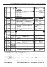
Only pulse signal of 0.5 second or more for Start/Stop sig-
nal can actually control the compressor at remote opera-
tion.
If such signal from remote place is a level signal (make
contact), following failures can happen:
(1) The unit automatically starts operation by setting the
remote operation switch if start/stop is not canceled.
(Operation by other than intentional action.)
(2) When shutdown happens, the unit will start again by
pressing the
RESET
button on the instrument panel if
the operation signal by remote control is not canceled.
(3) Even though remote control for starting the unit is tried
at the site, the unit can not start without operation sig-
nal at REMOTE given. (No independent operative
manipulation cannot be achieved at the site.)
(4) Despite the stop operation at the site, the unit does not
stop if REMOTE operation and stop signal are not can-
celled.
(The unit stops while pressing the
STOP
button, and
starts again when the button is released.)
7.6.6 In case of Remote Operation
In case the compressor is controlled for its start and
stop by the remote operation, it is required to connect
signal lines from remote place to the terminal board
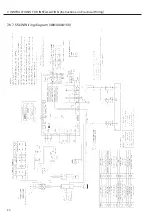
inside the starter panel. See the figure “TB-1 terminal
part” in the wiring diagram in pages 40 through 41.
If fixing the setting to remote, set F005 .
For further information on a remote operation,
see
p. 16.
One dry contact for each of operation and shutdown is
prepared at the “a (normal open)” contact. Rated cur-
rent is AC250V 0.5A.
IMPORTANT
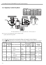
(5) When you check the performance of the capacity
control system in an initial startup operation, setup
the blow-off stop valve that is mounted at the sec-
ondary part of the air receiver tank. If you have to
use the alternative stop valve at the discharge outlet
of the
HISCREW
, close it slowly and gently.
Closing it violently may cause the relief valve to
operate or release the internal pressure. (This is not
abnormal because the motor speed control system
delays responding to a sudden change in pressure.)
When the multiple
HISCREW
s are operated in par-
allel, they control a capacity independently from
each other. Before proceeding to perform an initial
star tup operation, therefore, you must know a
capacity control feature that varies depending on
the type of
HISCREW
, and adjust the pressure set-
tings of each unit so that the
HISCREW
s can load
and unload in a scheduled order.
(6) The DCBL controller performs a quick switching
action that causes the input side to produce a har-
monic distortion and the output side to produce a
high-frequency noise and a leakage current.
The Vplus
HISCREW
contains a DC reactor to sup-
p r e s s a h a r m o n i c d i s t o r t i o n . I t f e a t u r e s a
shortlength wire to the motor and is shielded by
the enclosure panels, which makes a highfrequency
noise and a leakage current affect negligibly.
Depending on the stray capacitance of the power
cord, however, the earth leakage relays and/or cir-
cuit breakers may malfunction. Therefore, use the
necessary noise filters etc. that support the inverter.
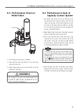
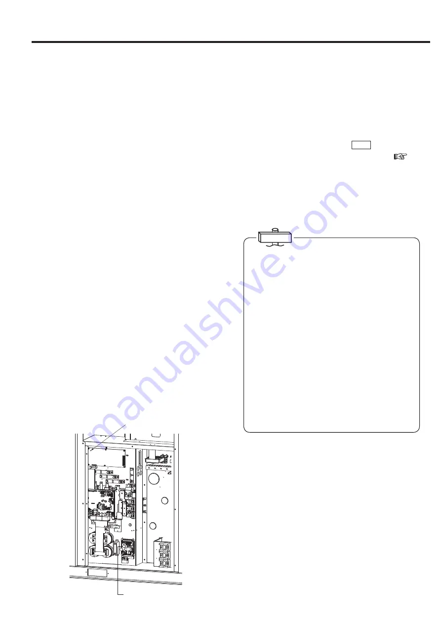
Charge Lamp(Fan inverter)
(Make sure that it is off)
Charge Lamp(Controller)
(Make sure that it is off)
39
7. INSTRUCTIONS FOR INSTALLATION [Instructions on Electrical Wiring]

