45
8. PERIODIC MAINTENANCE [Relief Valve, Capacity Control System]
8.5
Performance Check of
Capacity Control System
①
Gradually close the stop valve on discharge side
(located after the air receiver tank) to raise the dis-
charge air pressure. When the discharge air pres-
sure rises to the target pressure whatever you have
set, the inverter operates and starts dropping the
motor’s operating frequency.
②
Immediately when the motor's operating frequency
drops to 40 Hz, fully close the stop valve.
③
The suction throttle valve works and releases the
compressed air in the oil separator tank to the
atmosphere. Using the oil separator tank internal
pressure gauge, check the pressure in the oil sepa-
rator tank is stabilized at or below 0.15 MPa.
④
Fully open the stop valve on discharge side within 3
minutes after the I-mode capacity control is activat-
ed. Make sure that the air end reloads accordingly.
・
If the air receiver tank capacity on the discharge side is
less than recommended capacity, the air end reloads
before the pressure in the oil separator tank becomes
stable pressure.
・
Do not operate the stop valve immediately after stop-
ping the
HISCREW
. Otherwise the motor’s operating fre-
quency may fluctuate and/or the relief valve may oper-
ate.
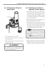
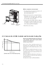
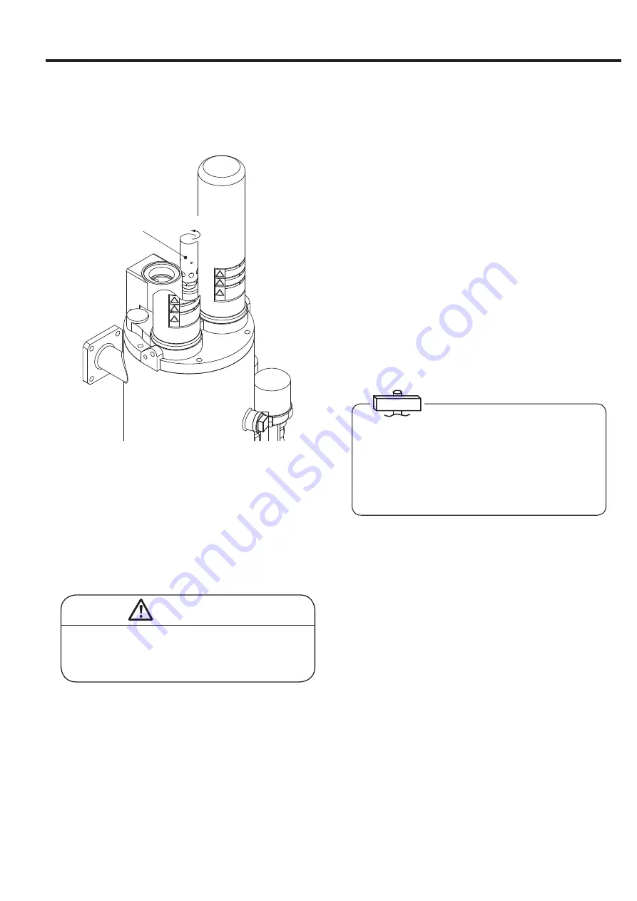
8.4
Performance Check of
Relief Valve
Relief Valve
Open
①
Set Discharge air Pressure to 0.7MPa.
②
Open the front door and turn the cup of the relief
valve anti-clock wise.
③
If the compressed air comes out, turn the cup of the
relief valve clock wise.
IMPORTANT
WARNING
Do not place your face near Relief Valve when
to check its performance. Compressed air can
come out and it is dangerous.


