Connectors x 8
Tuner PWB
Flat cable
DSP PWB
Video PWB
Digital PWB
Z
x 1
Flat Cable x 1
10
x 6
8
x 3
9
x 1
7
x 5
18
x 4
6
x 1
7
Claws (PWB Support)
8
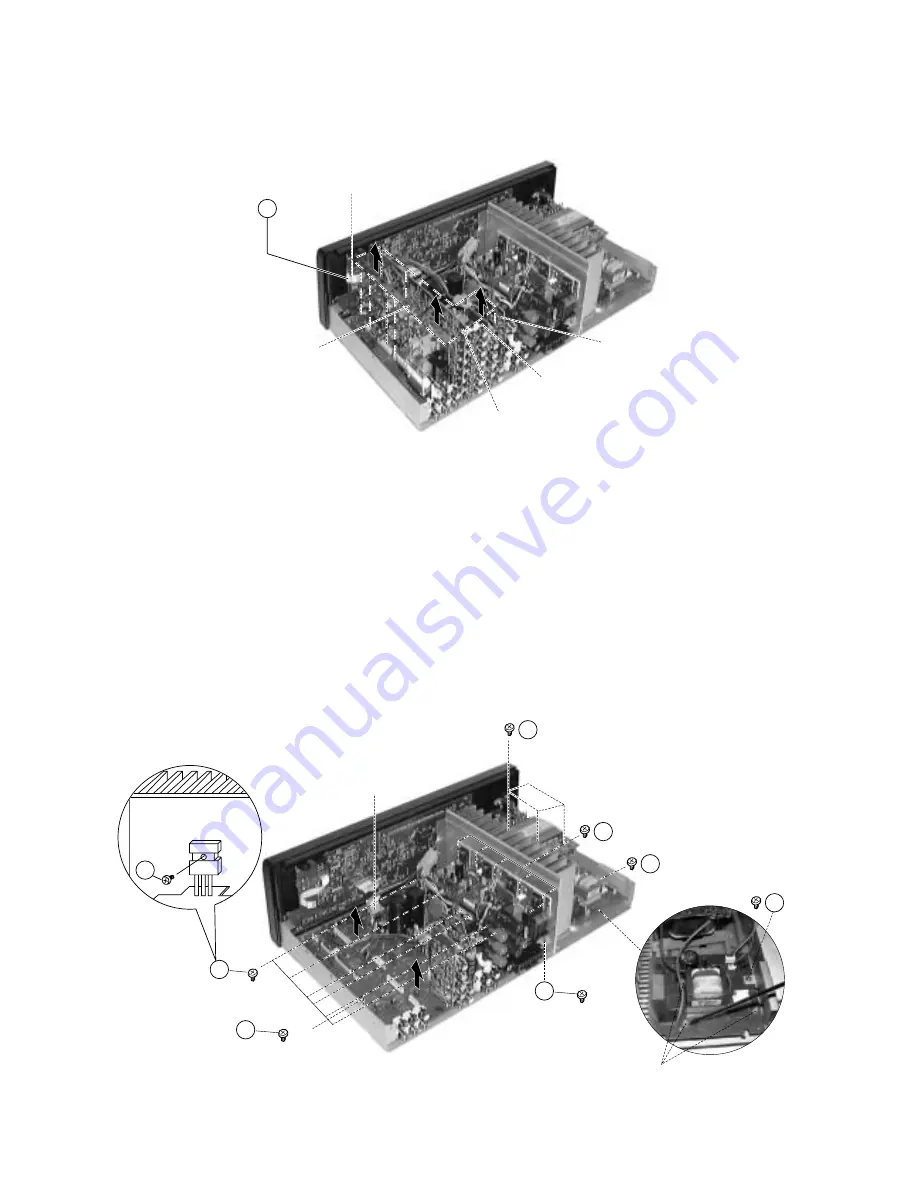
3. Removal of Tuner/DSP/Video/Digital PWB Board
(a)Remove the Flat cable Z at the Tuner PWB.
(b)Gently pull the Tuner/DSP/Video PWB Board upwards to detach 8 connectors from Main PWB Board.
(c)Detach the connector from DSP PWB Board to remove the Digital PWB.
4. Removal of Heat Sink and Transformer
(a)Invert the Bottom Chassis, remove 2 screws 5 connect to the heat sink. (Fig. 5)
(b)Remove 4 screws 6 and pull the transformer upward together with the Power PWB section.
5. Removal of Power PWB Board
(a)Remove 1 screw 7 from the Bottom Chassis at the side.
(b)Release board from its 3 holding claws (PWB SUPPORT) and gently pull the board free.
6. Removal of Main PWB Board
(a)Detach Flat cable from FL PWB Board.
(b)Remove 6 screws 8 to release the transistors from the heat sink.
(c)Remove 3 screws 9 to release the bracket from the heat sink.
(d)Remove 1 screw ! to release the main PWB from the Bottom Chassis.
7. Removal of Surround PWB
(a)Remove 5 screws ~ to release surround PWB from the heat sink.
Fig. 3
Fig. 4
Summary of Contents for HTA-DD1E
Page 8: ...17 x 4 10 Removal of Foot a Remove 4 screws to remove foot Fig 7 ...
Page 11: ...SM0102 WIRING DIAGRAM ...
Page 12: ......
Page 13: ...SM0102 TUNER PCB ...
Page 14: ...SM0102 SURR PCB ...
Page 15: ...SM0102 DSP PCB ...
Page 16: ...SM0102 FL PCB ...
Page 17: ...SM0102 POWER PCB ...
Page 18: ...SM0102 VIDEO PCB ...
Page 19: ...SM0102 SPJK PCB ...
Page 20: ...SM0102 SW H P PCB ...
Page 21: ...SM0102 DIGITAL IN PCB ...
Page 22: ...SM0102 MAIN CIRCUIT ...
Page 23: ...SM0102 DISP TONE CIRCUIT ...
Page 24: ...SM0102 SURROUND MAIN AMP CIRCUIT ...
Page 25: ...SM0102 TUNER VOLUME CIRCUIT ...
Page 26: ...SM0102 DSP CIRCUIT ...
Page 27: ...SM0102 POWER SUPPLY VIDEO CIRCUIT ...
Page 28: ......
Page 45: ...MEMO ...


