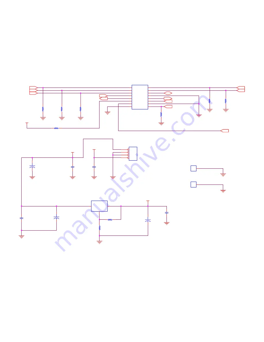
AMP SCHEMATIC INPUT CONNECTOR
POWER_ON_RST
+3.3V
+2.5V
+28V
+3.3V
R1
NS
0000-0603
R2
NS
0000-0603
R3
NS
0000-0603
R37
10K
0000-0603
U1
LM1117-ADJ
3
2
1
IN
OUT
AD
J
JP1
JS-1120-04
1
2
3
4
C7
100NF
Y5V
EIA0603
R4
NS
0000-0603
H2
DDX2060HS
1
R5
NS
0000-0603
R6
NS
0000-0603
H1
DDX2060HS
1
J1
87256-1611
INPUT CONNECTOR
1
3
5
7
9
11
13
15
2
4
6
8
10
12
14
16
+
C6
100UF
10V
100UF-ELEC-16V-RADIAL
C2
100NF
Y5V
EIA0603
R8
154
0000-0805
+
C8
100UF
10V
100UF-ELEC-16V-RADIAL
C4
100NF
Y5V
EIA0603
C3
100NF
X7R
EIA0805
R7
150
0000-0805
+
C1
100UF
10V
100UF-ELEC-16V-RADIAL
PWRDWN
TWARN2
LRCK
SCL
SDATA2
SDA
SDATA1
MCLK
SDATA0
BICK
TWARN1
POWER_ON_RST
Summary of Contents for HTD-K180E
Page 4: ...2 SYSTEM BLOCK DIAGRAM and MT1379 PIN DESCRIPTION 2 1 MT1379 PIN DESCRIPTION ...
Page 5: ......
Page 6: ......
Page 7: ......
Page 8: ......
Page 9: ......
Page 10: ......
Page 11: ......
Page 12: ......
Page 13: ...2 1 SYSTEM BLOCK DIAGRAM System block diagram is shown in the following figure ...
Page 21: ...Pay attention the left side Select CD and CD_ROM ISO on the upper left side of screen ...
Page 22: ...Select No Multisession ...
Page 23: ...Format is Mode 1 ...
Page 24: ......
Page 25: ...Leave the dates as it is ...
Page 26: ...Leave it as it is ...
Page 27: ...Click the New on the upper right corner of the screen ...
Page 29: ...Click the Burns the current compilation ...
Page 30: ...Then you will see this screen and click the Burn on the right upper side of screen ...
Page 32: ......
Page 33: ......
Page 34: ......
Page 35: ......
Page 36: ......
Page 37: ......
Page 38: ......
Page 39: ......
Page 40: ......
Page 41: ......
Page 48: ...THE UPDATED PARTS LIST FOR THIS MODEL IS AVAILABLE ON ESTA ...


