Travelstar 5K160 (PATA) Hard Disk Drive Specification
59
/
188
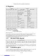
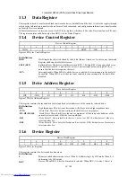
11.3 Data
Register
This register is used to transfer data blocks between the device data buffer and the host. It is also the register through
which sector information is transferred on a Format Track command, and configuration information is transferred on
an Identify Device command.
All data transfers are 16 bits wide, except for ECC byte transfers, which are 8 bits wide. Data transfers are PIO only.
The register contains valid data only when DRQ=1 in the Status Register.
11.4 Device
Control
Register
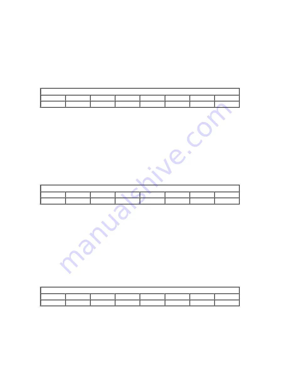
Device Control Register
7 6 5 4 3 2 1 0
HOB
- - - 1
SRST
-IEN
0
Figure 18 Device Control Register
Bit Definitions
HOB
HOB (high order byte) is defined by the 48-bit Address feature set. A write to any Command
Register shall clear the HOB bit to zero.
SRST (RST)
Software Reset. The device is held reset when RST=1. Setting RST=0 reenables the device.
The host must set RST=1 and wait for at least 5 microseconds before setting RST=0, to
ensure that the device recognizes the reset.
-IEN
Interrupt Enable. When IEN=0, and the device is selected, device interrupts to the host will
be enabled. When IEN=1, or the device is not selected, device interrupts to the host will be
disabled.
11.5
Drive Address Register
Drive Address Register
7 6 5 4 3 2 1 0
HIZ
-WTG
-H3 -H2 -H1 -H0 -DS1
-DS0
Figure 19 Drive Address Register
This register contains the inverted drive select and head select addresses of the currently selected drive.
Bit Definitions
HIZ
High Impedance. This bit is not device and will always be in a high impedance state.
-WTG
-Write Gate. This bit is 0 when writing to the disk device is in progress.
-H3,-H2,-H1,-H0
-Head Select. These four bits are the one's complement of the binary coded address of the
currently selected head. -H0 is the least significant.
-DS1
-Drive Select 1. Drive select bit for device 1, active low. DS1=0 when device 1 (slave) is
selected and active.
-DS0
-Drive Select 0. Drive Select bit for device 0, active low. DS0=0 when device 0 (master) is
selected and active.
11.6 Device
Register
Device/Head Register
7 6 5 4 3 2 1 0
1 L 1
DRV
HS3
HS2
HS1
HS0
Figure 20 Device Register
This register contains the device and head numbers.
Bit Definitions
L
Binary encoded address mode select. When L=0, addressing is by CHS mode. When L=1,
addressing is by LBA mode.
DRV
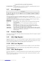
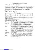
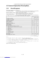
Device. When DRV=0, device 0 (master) is selected. When DRV=1, device 1 (slave) is

