background image

Service Manual

HITACHI

Printer

Model PH

Revision      Aug. 2011
Version        First edition

Summary of Contents for IJ PH

Page 1: ...Service Manual HITACHI Printer Model PH Revision Aug 2011 Version First edition ...

Page 2: ... Revision of PH service manual Revision Chapter Revised Page ...

Page 3: ...tage confirmation 2 8 2 3 3 Phase margin test 2 9 2 3 4 Auto phase gain adjustment 2 12 2 3 5 Level sensor confirmation 2 14 2 3 6 Heating unit confirmation 2 15 2 4 Test of solenoid valve pump 2 16 2 5 Download 2 18 2 6 Calibration of viscometer 2 20 2 6 1 Calibration of viscometer 2 20 2 6 2 Confirmation of the ink viscosity coefficient 2 22 2 6 3 Operation test of viscometer 2 23 2 7 Ink concen...

Page 4: ...wer supply 3 30 3 3 7 Fan Replacement Procedure 3 31 3 3 8 Exhaust Filter Replacement Procedure 3 33 4 Maintenance of Circulation System 4 1 4 1 General Structure of Circulation System 4 1 4 2 Main Ink Tank Replacement Procedure 4 4 4 3 Pressure Relief Valve Replacement Procedure 4 6 4 4 Joint Structure and Handling 4 8 4 5 Pump Unit Replacement Procedure 4 10 4 6 Solenoid Valves Replacement Proce...

Page 5: ... group Replacement Procedure 5 13 5 8 Head base Replacement Procedure 5 14 5 9 Replacing EZJ98 Board APH Sensor Board 5 16 6 Troubleshooting 6 1 6 1 Troubleshooting List 6 1 6 2 Faults Ink stop type 6 3 6 3 Faults Print stop type 6 22 6 4 Warning conditions printing continuously performed 6 33 6 5 Faults No on screen indications 6 43 6 6 Miscellaneous 6 53 7 Attached Drawing 7 1 7 1 Circulation sy...

Page 6: ...t performing an incorrect handling procedure is ignored CAUTION is used to indicate the presence of a hazard which may cause personal injury or property damage if the warning against performing an incorrect handling procedure is ignored WARNING CAUTION If the warning in the CAUTION category is ignored serious results may occur depending on the situation After the manual has been read it must be st...

Page 7: ...revent it from filling with organic solvent vapor Do not insert tweezers a screwdriver or any other metal article into the ink ejection hole in the end of the print head When the printer is ready to print a high voltage approximately 6 kV is applied to the deflection electrode section in the print head Exercise caution to avoid electric shock injury and fire Be sure to shut off the power before re...

Page 8: ...the print head Ink or makeup may enter your eyes or mouth or soil your hands or clothing If any ink or makeup enters your eyes or mouth immediately flush with warm or cold water and consult a physician Before servicing the printer be sure to stop the ink ejection Because ink or makeup may splash into your eyes or mouth or onto your hands or clothing If any ink or makeup enters your eyes or mouth i...

Page 9: ... of ink or makeup inside the printer while the printer is running or being maintained wipe it off promptly with wiping paper or something similar Then with the maintenance cover open stop the printer power it down and repair the leak Continuing operation with a leak of ink or makeup will cause an anomaly resulting in abnormal printing Ink and makeup are flammable They may therefore catch on or cau...

Page 10: ...rise and makeup could spurt out when the outside cover is removed Therefore when unplugging do not hold the bottle near your face place the can on a level surface open while covering the opening with a rag etc Ink and makeup must be stored as flammable liquids Storage must comply with local regulatory requirements Consult the appropriate regulatory agency for further information Ink and makeup mus...

Page 11: ...ricity When handling PC boards and electric parts remove the static electricity by wearing a suitably grounded anti static wrist band A touch panel is employed for data entry to operation screen When manipulating the Touch panel use only fingers If the touch panel is operated with metal and or sharp objects such as ball point pen it may malfunction or break down CAUTION 1 6 ...

Page 12: ...1 2 Structure of each part in the main body 1 2 1 External views PH D 1 7 Exhaust duct connection port Air purge connection port See section 1 2 6 Print head air purge in the instruction manual ...

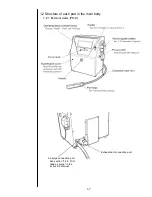
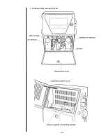
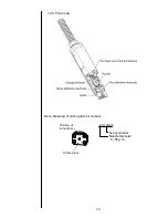
Page 13: ...1 2 2 Main body internal PH D 1 8 ...

Page 14: ...1 2 3 Print head 1 9 1 3 5 Print head Note Meaning of orifice plate lot number 6 A12345 Serial number Nozzle diameter 6 65μm Position of lot number Orifice plate ...

Page 15: ... following conditions besides the above mentioned conditions Standard UL and CUL recognition parts Rating 125V More than 7A Plug NEMA5 15P Cable Type SJT 18AWG More than 60 degrees C Cable length 1 5 to 4 5 m 1 10 min18 7 to 10 38 5 44 5 Max 25 Max60 Max30 Pay attention to the direction of the cable Unit mm Be sure to use an appropriate plug and connect a protective ground Place a wall socket in t...

Page 16: ... 1 Remove the Inlet cover Fixing screw 4 locations 2 Insert the power cable to the Inlet Inlet cover 4 fixed screws Power Cable 1 11 ...

Page 17: ... 3 Mount the inlet cover Tape the seal around the outside of the cable and as in the drawing and insert it into the holder as shown in above CAUTION Power cable Inlet Cover 1 12 ...

Page 18: ...tic acquisition This step is not required for the model PXR H 2 6 Calibration of viscometer 8 Pressure adjustment Set pressure to the standard value of every ink Instruction manual 7 12 Pressure adjustment 9 Adjustment of excitation voltage Touch screen operation automatic acquisition 2 3 1 Excitation adjustment 10 Adjustment of APH gain Touch screen operation automatic acquisition 2 3 4 Auto phas...

Page 19: ... setup Adjustment operational checkout Solenoid valve pump test Download 1 Select the maintenance in a menu and then select Password protection 2 Execute Limitation change and Input a password PHDO and press Enter password Caution 1 The password PHDO is a special password to enable the predetermined screen related to the control of IJP Do not tell this password to the customer 2 Even when the cust...

Page 20: ...the menu for the service personnel maintenance can be displayed Features of the service personnel maintenance mode No Functions Contents 1 Maintenance menu The second page of the maintenance menu can be displayed 2 User environment setup screen The excitation V ref warning can be displayed 3 Operation management screen The cumulative operating time can be changed 4 Operation management screen The ...

Page 21: ... software Use a CF card 32 MB 2GB Format FAT16 for memory card A memory card with the IJP system data hereinafter referred to as system data memory card is necessary to carry out the following service personnel maintenance works No Functions Contents 1 System environment setup The memory card is necessary to change the nozzle diameter The card is not required for other setting 2 Download Data for ...

Page 22: ...nvironment setup at the second page of the service maintenance work screen When the previous menu and the next menu are not displayed in the maintenance work menu set to the service personnel maintenance mode by the password protection 2 Set values using the numeric Decrement or Increment key When the ink type is set an initial value is automatically set With respect to the initial value refer to ...

Page 23: ...68 9 38 35 0 JP K87 68 9 39 40 0 JP K88 68 9 45 35 0 JP K90 68 9 41 35 0 JP Y91 68 9 29 35 0 JP F92 68 9 42 35 0 JP Y94 68 9 44 35 0 JP B95 68 9 47 35 0 JP F97 74 0 55 35 0 JP K101 68 9 54 40 0 JP K106 68 9 56 35 0 65 µm Note 1 When the ink type is set an initial value is automatically set With respect to full details about the excitation curve refer to the attached figure 8 6 2 The excitation cur...

Page 24: ...creen When the previous menu and the next menu are not displayed in the maintenance menu set to the service personnel maintenance mode by the password protection 2 Press Excitation adjustment When the screen is switched press Automatic adjustment The excitation voltage is automatically adjusted inside the IJ printer During the automatic adjustment the processing state is displayed to be In progres...

Page 25: ... the automatic adjustment the manual adjustment key is displayed When the manual adjustment key is pressed a numerical value is manually put into the excitation voltage adjusted value and the Apply key is pressed the excitation voltage value is increased and decreased Confirm a waveform of TP14 excitation voltage of the EZJ106 board by an oscilloscope Model Vp p PH D 360 20V With respect to positi...

Page 26: ... Charge voltage confirmation Since the voltage for the confirmation is output for 3 minutes measure the TP12 on the EZJ 106 board using an oscilloscope and confirm that the TP12 is in the range of DC 250V plus or minus 15V After the completion of the confirmation the work can be stopped before the passing of 3 minutes by pressing the Abort key With respect to the password protection refer to 2 1 s...

Page 27: ...setting of a standby state perform the work of this test as follows 1 Press adjustment operational checkout at the second page of the service maintenance screen When the previous menu and the next menu are not displayed in the maintenance menu set to the service personnel maintenance mode by the password protection 2 Select Phase margin test With respect to the password protection refer to 2 1 set...

Page 28: ...s selected the following figure is displayed and the printing phase is sequentially printed from 0 phase to 15 f phase every time Start Printing is pressed 16 printings in total form one cycle When the Sensor is selected the printing phase is sequentially printed from 0 phase to 15 f phase every time the sensor is input 16 printings in total form one cycle 2 10 ...

Page 29: ...hich is set at present 16 phases in total a phase determined to be most suitable from 0 to f any one from 0 to f When selecting Data to be displayed a printing is performed under the printing conditions printing contents set at present 4 Determination method of test Observing the print phases of from phase 0 to phase 15 f when a printing is not normally performed in the range of one or more phases...

Page 30: ... 2 3 1 Excitation adjustment And perform again after setting the optimal excitation voltage 1 Press adjustment operational checkout at the second page of the service maintenance screen When the previous menu and the next menu are not displayed in the maintenance menu set to the service personnel maintenance mode by the password protection 2 Press Auto phase gain adjustment When the screen is switc...

Page 31: ...utter part is made dirty with ink or makeup ink When dirtiness or the like is present wash the periphery of the gutter part surely dry it and then perform the automatic adjustment again Numerical values of the auto phase gain value can also be input by a ten key To the value set at present if the auto phase gain value is set large the gain becomes high whereas if it is set small the gain becomes l...

Page 32: ... the service maintenance screen When the previous menu and the next menu are not displayed in the maintenance menu set to the service personnel maintenance mode by the password protection 2 Press Level sensor confirmation The level sensor operation state is displayed Detected The sensor detected the level The ink and the makeup ink are present Undetected The sensor did not detect the level The ink...

Page 33: ...temperature The ambient temperature is displayed Heating unit temperature The temperature of the heating unit is displayed The temperature of the heating unit will be higher than the ambient temperature when the heating unit is activated Heating unit status Indicates whether the heating unit is activated or deactivated With respect to the password protection refer to 2 1 setting of service personn...

Page 34: ...ce personnel maintenance mode Perform this test in a stop state In an operating state only an operating state is displayed 1 Press solenoid valve pump test at the second page of the service maintenance screen When the previous menu and the next menu are not displayed in the maintenance menu set to the service personnel maintenance mode by the password protection The operating state of the solenoid...

Page 35: ... Stop The pump is stopped 2 When pressing Back the screen returns to the maintenance menu screen Caution The pumps and solenoid valve can be operated simultaneously however operate them with care when the solenoid valves are turned on while pump is activated because it is not a steady operation 2 17 ...

Page 36: ...card or circuit boards In case the customer protect maintenance works by a password unlock the password before the download and set a password again after the download is completed 1 Be sure to turn off the power 2 Insert the memory card with the IJP system data into the slot 3 Turn on the power Start the download automatically when turning on the power Take care that in this case the download pro...

Page 37: ... in the IJ printer the language is automatically changed to English when after downloading Refer to the following example Example Languages registered in the IJ printer Languages on the memory card 1 Spanish 1 English 2 French 2 Thai 3 Vietnamese 4 Arabic In this case English is displayed when after downloading If other language should be displayed please perform language registration again System...

Page 38: ... the viscometer can be done regardless of the ambient temperature 1 Turn on the power 2 Press Viscometer calibration at the second page of circulation control on the user maintenance screen and then press Start Continue 3 Press Start calibration During the viscosity calibration the processing state in progress is displayed Note at the calibration When the operation confirmation of the viscometer i...

Page 39: ...ears Normal measurement has not been executed Follow 4 9 Troubleshooting when fault occurs in viscometer 5 Press OK If the OK key is pressed when the process status is normal end the coefficient will be registered and the circulation control screen will be displayed Note at the calibration The coefficient will not be registered when Cancel is pressed instead of OK key Status XXXXXX ...

Page 40: ...efficient is not necessary to be changed usually Be sure to perform the viscometer calibration after the viscometer is changed This appears on the Unit information screen on the second page of the Service maintenance screen The coefficient is printed Check mark is not printed for the viscometer of PH D Coefficient confirmation method Status XXXXXX X No Check mark Viscometer No ...

Page 41: ...Viscometer calibration on page 2 of circulation control of service maintenance screen 2 Press Operation test 3 When the test is complete the current ink viscosity will appear If the process status is fault and message Check viscometer for any defect appears normal measurement has not been executed Follow 4 9 Troubleshooting when fault occurs in viscometer 4 Press Cancel to restore the original scr...

Page 42: ...stem environment setup and Start Continue in the maintenance menu and then the Circulation env setup screen is displayed 2 Press either 0 Disable or 1 Enable 0 The ink concentration is controlled by the dot count control without measurement of the ink viscosity Dot count control Amount of ink which is used for printing and vaporized makeup ink are automatically refilled 1 The ink concentration is ...

Page 43: ...g to the contents described in 3 2 1 EZJ124 board and 3 3 1 EZJ93 board 1 Press the System reset on the second page of the Service maintenance screen In case the Prev menu and Next menu are not displayed on the maintenance menu change the menu to the Maintenance mode by service personnel with Password protection A confirmation message appears 3 Press OK Wait for a minute is displayed After the com...

Page 44: ... from memory card to IJP Data type Copy data User pattern User patterns alphanumeric patterns Print data Print data Substitution rules User data Print data Substitution rules User patterns alphanumeric patterns Unit specific data Unit specific data Ink viscosity coefficient APH gain User environment setup etc When Maintenance is protected release the protection before backup and protect again afte...

Page 45: ...data on the Auxiliary function menu screen The Copy data screen then opens 6 Press Mem card Printer and select a direction of copy 7 Press User data Unit specific data 8 Press Overwrite copy 9 Press Start copy 10 After the copying is over turn off the power 11 press the ejector button and take the memory card out of the slot ...

Page 46: ...coefficient Ink viscosity coefficient can be set in this screen without Calibration of viscometer 1 Turn on the power 2 Put it into the Service personnel maintenance mode by using Password protection 3 Press the Unit information on the second page of the Service maintenance screen Status XXXXXX X ...

Page 47: ...setting is displayed at the Service personnel maintenance mode and it is not displayed at the User maintenance mode 1 Put it into the Service personnel maintenance mode by using Password protection 2 Press User environment setup at the Environment setup menu 3 Change the setting value of the Product speed matching error Caution Even if a condition for the warning happens and the print disordered t...

Page 48: ...Insert the memory card with the IJP system data into the slot 3 Turn on the power 4 Press Select language In case that the languages in the memory card are not displayed on the screen put it into the Service pesonnel maintenance mode by using Password protection 5 Point the cursor to the Language 1 and press Prev Language or Next Language and select a desirable language System data memory card Cau...

Page 49: ...hen the language of screen is Japanese or simplified characters 7 Press Save 8 Select the language 2 in the same way 9 After the language registration is completed turn off the power 10 Press the ejector button and take the memory card out of the slot System data memory card Caution After changing the Input mode execute System reset on the second page of the service maintenance screen In case of n...

Page 50: ...Unit Sensor Fault 067 Viscosity Readings Out of Range 018 F Memory Fault C 068 High Ink Concentration 019 F Memory Fault 9 069 Low Ink Concentration 020 F Memory Fault M 070 021 Hardware Error C 071 022 Internal Communication Error S 072 023 073 024 Ink Heating Current Fault 01 074 025 Ambient Temperature Sensor Fault 075 026 Cooling Fan Fault 076 027 077 028 078 029 079 030 F Memory Fault S 080 0...

Page 51: ...ernal Communication Error 015 112 External Communication Error 016 186 113 External Communication Error 017 187 Ink Temperature Correction Notice 114 External Communication Error 018 188 115 External Communication Error 019 116 External Communication Error 020 117 External Communication Error 021 118 External Communication Error 022 119 External Communication Error 023 199 120 External Communicati...

Page 52: ...em data is stored 3 Turn on the power 4 Press Option setup at the second page of the service maintenance work screen When Prev menu and Next menu are not displayed in the maintenance work menu set to the service personnel maintenance mode by the password protection When a memory card which IJP system data is stored is not set Option setup button is not displayed SOP0 2 SOP0 3 SOP0 4 SOP0 5 SOP0 8 ...

Page 53: ...f the setup the screen returns to the service maintenance screen 7 Turn off the Power 8 Press the ejector button and take the memory card out of the slot 9 Turn on the power 10 Check the function of the software option Caution Turn off after more than 10 seconds of the returning to the service maintenance screen ...

Page 54: ...sh Language2 none Input mode 1 Reinstall from language select screen Option setup Not supported Back up data Print data Original shipment state User pattern Original Standard character Original User environment setup Original System environment setup Original Communication environment Original Operation setup Original Reinstall Ink operating time Cumulative op time and Pint count Alarm history All...

Page 55: ...al number from Unit information screen Go to step 9 when the memory card include back up data 9 Turn off the power 10 Press the ejector button and take the system data memory card out of the slot 11 Insert a memory card into the slot 12 Copy data from memory card to IJ printer after reference to 2 9 back up 13 Reinstall all items which are not include of back up data on the list of previous page 1...

Page 56: ... EZJ93 board EZJ95 board Multiple power supply High voltage power supply When opening the cover of the controller part and the engine part be sure to cut off the power supply The unit has such a part that high voltage is applied When performing the adjustment in a state where the cover is opened be fully careful about an electric shock Caution against electric shock Engine part cover opening state...

Page 57: ...g screws Two locations Controller part Cover fixing screws Two locations Controller part cover opening state LCD backlight power supply EZJ124 board Touch panel operation side EZJ97 board Battery LCD Backside of panel ...

Page 58: ... EZJ124 board is replaced in a state allowing NO back up follow the Replacement procedure of EZJ124 board in a state allowing NO back up in the page 3 5 2 Turn off the power 3 Replace the EZJ124 board Do not replace the EZJ93 board simultaneously 4 Before turning on the power insert the system data memory card into the slot of EZJ124 board 5 Turn on the power With the system data memory card inser...

Page 59: ...from Option setup management screen if necessary Refer to 2 14 Software option setup 13 Recover the data from the back up memory card by using the copy data function From the memory card to the IJP 14 As the operation management the parts usage time management password setup and the unit information are not backed up by the copy data function Set them again Note 1 The print data are the print desc...

Page 60: ...ption screen is displayed 8 Execute Select language on the auxiliary function screen Refer to 2 12 Language registration 9 Execute System reset on the second page of the service maintenance screen 10 Perform setup and or adjustment according to the following table No Item Reference manual 1 Calibrate touch screen coordinates Instruction manual 5 4 Calibrating the Touch Screen coordinates 2 Touch s...

Page 61: ...trast adjustment VR Connector for touch panel Connector for EZJ93 board Connector for battery Setscrews 5 locations Setscrews 5 locations Setscrews 5 locations Setscrews 5 locations Setscrews 5 locations Connector for LCD harness CF card connector TP11 TP12 TP60 TP10 ...

Page 62: ... using tape etc 1 If mixed with other metal or battery uninsulated battery may cause heating fire or explosion 2 Do not put the battery into fire 3 If battery not used or battery of 3V or more is to be disposed of connect resistor of about 100 ohms between both terminals of battery and discharge for at least 48 hours Then confirm that the battery voltage is less than 3V and insulate electrodes usi...

Page 63: ...the touch panel to the predetermined connectors After the replacement setting the touch screen coordinates Set the date and time When inserting the touch panel connection cable into the connector on EZJ102 board always hold both sides of reinforced section for connection as shown in the figure so that the cable is not bent Caution CN2 CN1 With respect to the setting of date and time refer to the I...

Page 64: ...ions of the CCB cover and remove the CCB cover 3 Remove the fixing screw of the SUS ball chain and the fixing screw of the clamp and then remove the harness from the clamps 2 positions and remove the connector from CN3 Clamps 2 positions Fixing screws 4 pieces CCB Cover Harness Fixing screw SUS ball chain Connector CN3 Fixing screw Clamp Clamps 2 positions ...

Page 65: ...d remove EZJ124 board Battery connection cable CN2 Connector for EZJ97 board CN4 EZJ124 board EZJ97 board LCD Backside of panel Touch panel connection cable Battery Connector for LCD CN8 Fixing screws 5 pieces Controller part Hinges 2 potions Fixing screws 6 pieces When inserting the touch panel connection cable into the connector on EZJ102 board always hold both sides of reinforced section for co...

Page 66: ... the connector for EZJ97 board 7Disassemble the door lock assembly as the diagram below indicates Note When disassembling the door lock assembly do not lose the O ring S6 Door lock assembly Door lock assembly O ring S6 Connector for EZJ97 board Cover Cover Fixing screws 2pieces ...

Page 67: ...that the dusts doesn t enter between the front panel and the touch panel 10Return the unit to its original state by performing the procedure in reverse order Note Insert the connectors to right places EZJ97 board Fixing screws 2 pieces Front panel assembly LCD base Connector for EZJ97 board Before removing the LCD base confirm to remove the connector for EZJ97 board When the LCD base is removed wi...

Page 68: ... of the CCB cover and remove the CCB cover 3 Remove the fixing screw of the SUS ball chain and the fixing screw of the clamp and then remove the harness from the clamps 2 positions and remove the connector from CN3 Clamps 2 positions Fixing screws 4 pieces CCB Cover Harness Fixing screw SUS ball chain Connector CN3 Fixing screw Clamp Clamps 2 positions ...

Page 69: ...ve EZJ124 board Caution When inserting or removing the touch panel connection cable into the connector on EZJ124 board always hold both sides of reinforced section for connection as shown in the figure so that the cable is not bent Fixing screws 5 pieces Battery connection cable CN2 EZJ124 board EZJ97 board Connector for EZJ97 board CN4 LCD Backside of panel Touch panel connection cable Battery Co...

Page 70: ...nd the cover and remove the connector for EZJ97 board 7Remove the connector for LCD and the harness from the clamp and the connector for LCD backlight Connector for EZJ97 board Cover Fixing screws 2pieces Connector for LCD backlight Connector for LCD Clamp ...

Page 71: ...ve the fixing screws 12 pieces of the LCD base and remove the LCD base Door lock assembly Door lock assembly O ring S6 LCD base Connector for EZJ97 board Caution Before removing the LCD base confirm to remove the connector for EZJ97 board When the LCD base is removed with the connector connected the harness might be damaged Connector for EZJ97 board ...

Page 72: ...usts doesn t enter between the front panel and the touch panel 11 Return the unit to its original state by performing the procedure in reverse order Note Insert the connectors to right places LCD assembly Fixing screws 4 pieces Wear the gloves when replacing the LCD assembly Handling with bare hands leaves fingerprints on the surface of the glass Wipe off the dust on the glass before replacement C...

Page 73: ... 3 11 2 Turn off the power 3 Replace the EZJ93 board Do not replace the EZJ124 board simultaneously 4 Before turning on the power insert the system data memory card into the slot of EZJ124 board 5 Turn on the power With the system data memory card inserted Setting of the switch is not performed As for the copy data function see 2 9 Backup When replacing the EZJ93 board the memory card where the IJ...

Page 74: ...Unit information screen 12 Recover the data from the back up memory card by using the copy data function From the memory card to the IJP 13 As the operation management the parts usage time management password setup and the unit information are not backed up by the copy data function Set them again Note 1 The print data are the print description the printing specifications the print line the print ...

Page 75: ...displayed 8 Press the ejector button and take the system data memory card out of the slot 9 Execute System reset on the second page of the service maintenance screen 10 Perform setup and or adjustment according to the following table No Item Reference manual 1 Calibrate touch screen coordinates Instruction manual 5 4 Calibrating the Touch Screen coordinates 2 Touch screen setup Instruction manual ...

Page 76: ...3 21 EZJ93 board external views TP3 TP6 One setscrew Five studs for fixing EZJ106 Five studs for fixing EZJ106 Five studs for fixing EZJ106 Five studs for fixing EZJ106 Five studs for fixing EZJ106 ...

Page 77: ...diameter After replacing the board confirm the charging voltage Perform the excitation adjustment Perform the auto phase gain adjustment EZJ106 board external views With respect to the charging voltage confirmation refer to 2 3 2 Charging voltage confirmation With respect to the auto phase gain adjustment refer to 2 3 4 Auto phase gain adjustment The EZJ106 board has a portion where high voltage i...

Page 78: ...minals 2 and 3 closes as shown in the table at below regardless of whether the IJ printer is ready SW2 SW2 Set content Default Bit 1 Setting is performed according to the specification of OFF Bit2 the encoder Refer to the setting by types of the OFF Bit3 specification described below OFF Bit4 OFF Bit5 Power to the printed matter sensor from the IJ printer is set When supplying the power from the I...

Page 79: ... target detector is ON it is lighted LED2 Printing stop input When the printing stop signal input is ON it is lighted LED3 Rotary encoder input When the rotary encoder signal input for product speed matching is ON it is lighted LED4 Deflection voltage ON OFF input When the deflection voltage ON OFF signal input is ON it is lighted LED5 Reverse direction printing input When the reverse direction pr...

Page 80: ...3 25 3 25 Circuit diagram of EZJ95 ...

Page 81: ...ded parts Setting procedure 1 Save the current data to Memory card 2 Turn the power off 3 Remove electrical component cover fixed by the two screws and the plastic plate from the bottom it Hexagonal spacer 2 pieces Resin spacer 2 pieces Ferrite core 1 piece Screw 2 pieces As for the copy data function see 2 9 Backup Fixing Screw Electrical component cover Plastic plate Fixing Screw Electrical comp...

Page 82: ...ctor CN1 on the EZJ93 board and then attach the screws to the two hexagonal screws and tighten them 6 Change the switch setting as shown on the following page 7 Attach the electrical component cover EZJ95 board Hexagonal spacer Plastic spacer Board base EZJ99 board Connector CN1 EZJ93 board Screws Plastic spacer Plastic spacer ...

Page 83: ...stem reset 11 Return the backed up data to IJP 12 Turn the power off Connect wires from external devises to the TB1 depending on software options Attach the included ferrite core to the cables as below Applied wire size AWG26 14 0 4 mm 1 6 mm Peeling length of cables 9 mm As for the copy data function see 2 9 Backup As for the System reset see 2 8 System reset As for the software option setup see ...

Page 84: ... 12 V Set to OFF when using an external power supply Connect the external power supply 12 24 V to pin 1 of terminal board TB1 ON Bit 8 Reserve Set to OFF OFF Notes for replacement Be sure to turn power off when replacing the EZJ99 board Save the data on memory card by using the copy data function before replacing the EZJ99 board and be sure to recover the data after replacement As the operation ma...

Page 85: ... case where they are dusty The high voltage power supply has a portion where high voltage is applied When performing the adjustment or the like in a state where the operation panel cover is opened be fully careful about an electric shock Caution against an electric shock DC output for CN9 of EZJ93 board AC input for connection to the relay connector from the terminal Fixing screw 4 locations Fixin...

Page 86: ... the connector of the fan 3 wires black red and blue 4 pin connector 4 Remove the exhaust cover and the rear cover Caution Take care not to cause the removed connector of the fan to be caught Rear cover Fixing screw 15 locations Exhaust cover Fixing screw 4 locations The cover can be removed by loosing screws Fixing screw 2 locations Operation panel Electrical component cover Connector for the fan...

Page 87: ...6 Install a new fan by reversing the above procedure Caution Pay attention to the mounting direction of the fan air flow direction 7 Turn on the power supply and make sure that Cooling Fan Fault does not appear Exhaust cover Nut 4 pieces Filter cover Rear cover Fan Fan guard Fixing screw 4 pieces Wire mesh filter Exhaust filter Fan Label side Spacer Spacer ...

Page 88: ...operating environment condition Replace the exhaust filter at the same time with the air filter in every two times 1 Turn off the power supply 2 Remove the exhaust cover 3 Remove the fixing nuts 4 locations the filter cover and the exhaust filter Configuration of the model PH model Exhaust cover Red mark Nut 4pieces Washer 4pieces Filter cover Exhaust Filter Rear cover Fan Exhaust cover Fixing scr...

Page 89: ...l a new Exhaust Filter by reversing the above procedure The red mark side is the filter cover side There are a front side and a backside of the exhaust filter Place the red mark side toward the Exhaust cover Caution ...

Page 90: ...ning torque Part name used location Companion parts name Companion material N m kgf cm ICU base A PBT G30 1 7 0 3 17 3 3 ICU base B PBT G30 1 7 0 3 17 3 3 Front panel PP 1 33 0 22 13 6 2 2 Self tapping screw M4X12 attaching pressure system etc Main ink tank PP 1 33 0 22 13 6 2 2 Self tapping screw M4X16 attaching solenoid valve ICU base B PBT G30 1 7 0 3 17 3 3 Self tapping screw M4X12 attaching p...

Page 91: ... a safe place after removing the connection tube block 2 Remove the ink filter from the fixture and draw it out 3 Remove the fixing screws 2 pieces of the reservoir base and remove the reservoir base Reservoir base Fixing screw Ink reservoir Makeup ink reservoir Connection tube block Connection tube block Holder Ink filter ...

Page 92: ...nt 1 Perform the operations of 1 to 3 in 4 1 2 Approach to the parts on the front side of the equipment 2 Remove the fixing screws 2 pieces of the unit door and open the unit door Caution Take care not to cause the plumbing tube to be caught Unit door Fixing screw ...

Page 93: ...he drain tube 2 Turn off the power supply 3 Perform 4 1 3 Approach to the parts on the rear side of the equipment 4 Remove the wire connecting part screws 3 positions of the liquid level sensor in the main ink tank the recovery tube and the exhaust tube Fixing screw Exhaust tube Black long White Black short Recovery tube ...

Page 94: ... tank Caution Put wiping paper under the main ink tank to provide for an ink drip 6 Clean the portion stained with ink and then install the main ink tank by reversing the above procedure 7 Perform Ink refill and make sure that there is no ink leak Main ink tank Fixing screw Fixing screw ...

Page 95: ...under Pressure reducing valve to provide for an ink drip 4 Replace Pressure reducing valve and the O rings 3 pieces with new ones Caution Make sure to use O rings 4 7 3 pieces 5 Clean the O ring mounting positions of Pressure reducing valve joint PRV with makeup ink And set the O rings 3 pieces in the mounting positions of Pressure reducing valve joint PRV Pressure reducing valve Pressure reducing...

Page 96: ...Pressure reducing valve joint PRV 7 Mount Pressure reducing valve on Pressure reducing valve joint PRV by Nonsert M4x16 2 pieces Caution Be careful of the mounting direction of Pressure reducing valve Turn Al mark to the lower side 8 Perform Ink Replenishment and adjust the pressure Make sure that there is no ink leak Nonsert M4X12 Attaching pin Pressure reducing valve joint PRV Ink circulation un...

Page 97: ...the ICU joint at occurrence of damage 1 Mount the O ring on the ICU joint 2 Get the O ring wet with the makeup ink and then insert it into the connecting port of the circulation unit Caution If it cannot be inserted smoothly the O ring may bite Perform the operations starting from Step 1 once gain 3 Tighten the fixing screw Procedure for removing the ICU joint at occurrence of damage 1 Remove the ...

Page 98: ...e filter joint nut and remove the whole from the mounting part 2 Fix the end of the filter joint and loosen the tube block 3 Pull out the tube Assembling the filter joint 1 Mount the O ring on the filter joint 2 Get the O ring wet with the intensifier and install the ink filter and others together with the filter joint nut 3 Pass the tube through the tube lock 4 Insert the tube into the end of the...

Page 99: ...ires from the clamps 5 positions that fix them 5 Remove the connector that connects the motor 6 Remove the tubes 4 positions connected to the pump unit and remove the screws 2 positions that fix the pump unit on the door Remove the ICU joint to remove the tube shown by dashed line and loosen the tube lock to remove the others Connector for the motor Fixing screw Fixing screw Remove the ICU joint ...

Page 100: ...n ink drip 8 Clean the portion stained with ink and make sure that the O rings 4 positions are securely mounted in the concave parts of the lower side circulation unit Then install a pump unit by reversing the above procedure 9 Perform Ink refill and adjust the pressure Make sure that there is no ink leak 10 Reset the pump time to 0 on the Parts usage time management screen Insert the screwdriver ...

Page 101: ...ecute Gutter Cleaning No operation is required Take care about an ink drip MV4 Execute Ink drainage No operation is required Take care about an ink drip MV5 Execute Nozzle backwash No operation is required Take care about an ink drip MV6 Execute Ink drainage No operation is required Take care about an ink drip MV7 Execute Ink drainage Drain the ink in the main ink tank from the drain tube MV8 Exec...

Page 102: ...ned with ink and then install a solenoid valve by reversing the above procedure Caution Set the O ring in the groove of the solenoid valve securely Take care not to cause the O ring to fall off or bite 7 Reset the time of the corresponding solenoid to 0 on the Parts usage time management screen Fixing screw Solenoid valve O ring S16 O ring 4 7 O ring mounting groove ...

Page 103: ...e connector is provided on the rear side of the equipment 4 Remove the connector of the pressure sensor 5 Remove the screws 2 positions that fix the pressure sensor The pressure sensor can be removed Caution Put wiping paper under the solenoid valve to provide for an ink drip 6 Clean the portion stained with ink and then install a pressure sensor by reversing the above procedure Connector for the ...

Page 104: ...ief 2 Turn off the power supply 3 Perform 4 1 3 Approach to the parts on the rear side of the equipment 4 Remove the wire connecting part screws 3 positions of the liquid level sensor in the main ink tank and the exhaust tube Fixing screw Exhaust tube Black long White Black short Main ink tank ...

Page 105: ...ns that are connected to the circulation unit Caution Take care about an ink drip 6 Remove the clamps 5 positions that fix the wires 7 Remove the connectors of the electric parts motor solenoid valves pressure sensor level sensor and viscometer ...

Page 106: ...lation unit can be removed 9 Clean the portion stained with ink and then install the main ink tank by reversing the above procedure 10 Perform Makeup ink refill and then Ink refill Make sure that any ink or makeup ink leak does not occur at each connecting part Fixing screw Fixing screw ...

Page 107: ... recovery is made b Disassemble and clean viscometer Proceed with c if no recovery is made c Replace viscometer 2 Viscosity Readings Out of Range Estimated cause Ink adhered to the IN side of viscometer Troubleshooting Disassemble and wash viscometer Estimated cause Proximity sensor was faulty Troubleshooting Replace proximity sensor If there is no recovery with the above troubleshooting replace t...

Page 108: ...meter A Turn power on B Use Solenoid Valve Pump Test screen of Maintenance Work to turn on the pump to MV4 in that order and operate them for at least 10 seconds The ink remaining in viscometer will return to the main container C Turn power off 3 Unplugging connectors Caution Do not perform this work with power turned on Doing so will cause Viscometer Temperature Sensor Fault to occur Unplug the c...

Page 109: ...ut to the wiping paper C Make sure that no ink remains in viscometer and then pull out the cylinder If ink remains it will dirty the coil D Put the removed plunger and cylinder in a beaker filled with intensifier and wash them for at least 5 minutes using an ultrasonic washer Viscometer cover Three viscometer cover setscrews Coil Cylinder Plunger Two viscometer IN joint setscrews Thermistor setscr...

Page 110: ...edure A Set the O ring and squeezing pin on the viscometer OUT side and use the two setscrews to attach them to the circulation unit B Plug in the connectors of lead wires again C Connect the viscometer IN side tube mark G Note After reassembly it may be necessary to replace the ink and or calibrate the viscometer When disassembling and washing during installation Calibrate the viscometer without ...

Page 111: ... its original position referring to item 4 9 4 Take care not to forget to plug in the connectors of lead wires Caution After replacing the proximity sensor it is necessary to replace the ink and calibrate the viscometer see 2 6 Calibration of viscometer 4 9 6 Replacing thermistor A Remove the viscometer from circulation unit referring to item 4 9 1 B Remove the screw holding the thermistor fixing ...

Page 112: ...print head Loosen the tube lock and pull out the tube Caution Put wiping paper at the end of the tube to provide for an ink drip Fixing screw Operation panel Board cover High voltage wire APH signal wire EZJ106 board CN2 Charged signal wire EZJ106 board CN3 Excitation signal wire EZJ106 board CN5 Cover switch etc EZJ106 board CN7 FG wire Grounding Circulation line Pipe signal J Collection line Pip...

Page 113: ... in 4 from the rear side of the equipment 9 Remove the fixing screws 4 positions of the print head on the rear side of the equipment The print head can be removed from the equipment 10 Install a new print head by reversing the above procedure 11 Perform Ink Replenishment and adjust the pressure Make sure that there is no ink leak 12 Perform Excitation adjustment and Auto phase gain adjustment Fixi...

Page 114: ...ry or sticks The solenoid valve is operated but ink does not flow Refer to 4 12 Repairing method when the circulation route dry or sticks MV1 malfunctions When Open is executed on the Solenoid Valve Pump Test screen no operation sound is produced Replace or repair the solenoid valve MV1 Refer to 4 12 Repairing method when the circulation route dry or sticks The solenoid valve malfunctions MV9 malf...

Page 115: ...s faulty When the pump and then MV1 are turned on ink flows to the collation tube Solenoid Valve Pump Test screen Replace the solenoid valve MV6 The ink pressure does not increase Others The pressure sensor malfunctions Ink jets and printing can be performed but the pressure value is abnormal Replace the pressure sensor The pressure resistance of MV7 is faulty The makeup ink in the pipe N is sucke...

Page 116: ...ctions When Open is executed on the Solenoid Valve Pump Test screen no operation sound is produced Replace or repair the solenoid valve MV3 Refer to 4 12 Repairing method when the circulation route dry or sticks The circulation route clogs Clogging in the pipe or joint The nozzle can be flushed reversely and MV4 can be operated normally Refer to 4 12 Repairing method when the circulation route dry...

Page 117: ...nctions When Open is executed on the Solenoid Valve Pump Test screen no operation sound is produced Replace or repair the solenoid valve MV2 Refer to 4 12 Repairing method when the circulation route dry or sticks MV7 malfunctions When Open is executed on the Solenoid Valve Pump Test screen no operation sound is produced Replace or repair the solenoid valve MV7 Refer to 4 12 Repairing method when t...

Page 118: ...nnector is abnormal Part Check method Criterion Pump motor 1 Operate the pump on the Solenoid Valve Pump Test screen 2 Measure the voltage at pin No 5 wire red 20 V DC or more Solenoid valve 1 Replace the solenoid valve and the connector with another normal solenoid valve and connector 2 Make a check on the Solenoid Valve Pump Test screen Release the solenoid valve An operation sound can be confir...

Page 119: ... the Solenoid Valve Pump Test screen If an operation sound can be confirmed the repair work is completed If not replace the solenoid valve 4 12 2 Repairing method for the supply pump 1 Remove the tube connecting block of the ink reservoir and connect the hand pump 2 Operate the pump MV2 and MV6 in this order on the Solenoid Valve Pump Test screen 3 Apply pressure with the hand pump 4 If the makeup...

Page 120: ...rt up or Eject ink 2 After the pump is started operate it for about 10 minutes in the status where the pressure adjusting knob is turned completely clockwise to obtain the maximum pressure 3 Stop the pump and then execute Nozzle Backwash If suction from the nozzle can be confirmed the repair work is completed If the pump cannot be repaired repeat the same operations starting from 1 again If the pu...

Page 121: ...the head base rear cover Further packings are put also in the mating portion of the head base and the deflecting base 3 The APH sensor board EZJ98 board assembly for the phase matching is put in the recovery path on the head base rear surface 2 How to remove each cover 1 When the knurled screws are unloosened the head cover can be removed 2 When the setscrews are unloosened the heater cover can be...

Page 122: ...e OUT joint by a cutter or the like Caution When removing the nozzle OUT joint remove it so as not to pull the main body side tube Caution A If you scratch the coupling with a cutter or the like it may cause an ink leakage and so on B When removing a cut piece of the tube cut the tube piece and pull it off the coupling 5 Pull out the nozzle upward with a slope while taking up the front edge of the...

Page 123: ...able length and connect the nozzle OUT joint Caution A Get rid of the tube remaining on the joint in the 4 B When the tube is hardly put in the joint because it slips grasp the front edge of the tube by a JK wiper or the like and put it in the joint 8 Put the charged electrode in the new nozzle and fix the video signal wire on the charged electrode 9 Execute Ink stream alignment on the Circulation...

Page 124: ... 0 45 R27 0 255 68 9 0 35 B27 0 255 68 9 0 35 G27 0 255 68 9 0 35 K28 0 245 68 9 0 35 K31A 0 245 68 9 0 35 K33 0 255 74 0 0 35 Y37 0 255 68 9 0 35 K60 0 245 68 9 0 35 K61 0 245 68 9 0 35 K62 0 255 68 9 0 35 F63 0 255 68 9 0 35 T64 0 255 68 9 0 35 K65 0 255 68 9 0 35 K67 0 255 68 9 0 45 K68 0 245 68 9 0 35 R65 0 255 68 9 0 35 K69 0 255 68 9 0 45 K70 0 255 68 9 0 35 T71 0 255 68 9 0 35 K72 0 245 68 ...

Page 125: ...5 68 9 0 35 K87 0 255 68 9 0 40 K88 0 255 68 9 0 35 K90 0 255 68 9 0 35 Y91 0 255 68 9 0 35 F92 0 245 68 9 0 35 Y94 0 255 68 9 0 35 B95 0 245 68 9 0 35 F97 0 245 74 0 0 35 K101 0 255 68 9 0 40 K106 0 255 68 9 0 35 ...

Page 126: ...n after cleaning it is necessary to replace the deflection base Perform it by using the following procedure 1 Depressurize the printer 2 Remove all of the covers described in the item 5 1 3 Unscrew the nozzle setscrew the deflecting electrode setscrew and the charged electrode feed screw on the surface of the deflecting base 4 Unscrew the APH sensor setscrews high voltage electrical power lines se...

Page 127: ...crew part with silicon rubber according to the following procedure A Fill the top and bottom of the ring terminal with silicon rubber using a dispenser Caution a Hold the head as shown below in order to prevent the silicone from running Nozzle High voltage line terminal round terminal Dispenser Insert the tip of the dispenser into the downside of the terminal to fill the downside space High voltag...

Page 128: ...to 100mm away so as not to deform the tube by keeping it too close Silicone Filling Portion Hatching Portion The metallic portion of the high voltage line terminal portion should be completely hidden Rib of the base plate D section Fill it up to approximately the same height as the rib of the base plate so that the screw head will not be out Rib High voltage round terminal Fill up the downside of ...

Page 129: ...he high voltage electrical power line setscrew part it causes high voltage leak C When mounting the rear cover paying attention to pinching of the lead and gasket Knack of infusing the silicone When infusing the silicone into the dispenser perform it as shown below to purge air Metallic needle Cylinder Put the silicone in Place the needle on the upside Cylinder Downside is NG Wait until the silico...

Page 130: ...ealing valve 4 Unloosen the nozzle IN joint presser foot and the sealing valve presser foot A A filter is put in the terminal area inside the sealing valve of the nozzle IN joint 5 Take up the sealing valve remove the makeup ink IN joint and remove the sealing valve A Lift the fore of the sealing valve as in the drawing B When the O ring P2 2 is remained at the heating unit remove it Sealing valve...

Page 131: ...g the makeup ink on the O ring and confirm that the O ring does not jump out of the hole C Be careful not to apply the makeup ink to the A portion below 9 Attach the sealing valve presser foot and fix the sealing valve 10 Put the filter and the nozzle IN joint in this order and fix it by the nozzle IN joint presser foot A Refer to the nozzle replacement work sequence 11 Assemble the sealing valve ...

Page 132: ...emove the heating unit Caution Lead wires and tubes are laid over the heating unit When the heating unit is removed do not pull them accidentally 7 Prepare a new heating unit and put an O ring in the terminal area of the ink furnishing tube E Caution A Use an O ring of P 1 7 hole diameter about φ 1 6 B Be sure to put the O ring so as not to jump out of the hole of the joint portion 8 Attach the he...

Page 133: ...nvironment setup screen from the Maintenance menu screen and change the Ink temperature correction to 1 enable 15 Confirm the print state In the case where the set value of the excitation voltage is changed at the occurrence of fault reset the set value 5 7 Gutter base group Replacement Procedure When damaging the gutter and the gutter base the gutter base group must be replaced Perform it by the ...

Page 134: ...he fastening screw between the head base and the head cable and remove the head base 11 Attach a new head base Caution A Do not mix up lead wires and tubes which each is disposed on the front face nozzle side and the back face high voltage cable side Front face ink furnishing tube E makeup ink tube R circulation tube J air purge Back face excitation signal wire pull it out from the head base openi...

Page 135: ...dge of the head base 15 Attach the APH board and solder the video signal wire Caution A The construction of the video signal wire is as follows core wire signal side peripheral ground wire GND side B The core wire is very thin and therefore be careful to the breaking of wire Signal side soldering GND side soldering Heater Heater spacer Deflecting base Heater Heater spacer packing Heater packing De...

Page 136: ... so as not to crush a tube 20 Connect the excitation connector and attach all of covers so as not to enwind wires 5 9 Replacing EZJ98 Board APH Sensor Board 1 Remove the head cover and head base back cover 2 Use soldering iron to unsolder the coaxial cable Caution Do not apply excessive heat Doing so will melt the resin conductor which could cause a short circuit between the core wire signal line ...

Page 137: ...e heat Doing so will melt the resin conductor which could cause a short circuit between the core wire signal line and shielding wire ground 6 Perform the automatic phase gain adjustment Caution If the APH sensor is removed from head base for adjustment the insulation tube 5 mm long may become detached If it does be sure to reattach the insulating tube during reinstallation Screw for APH sensor Scr...

Page 138: ... Fan Fault 6 3 Faults Print stop type 6 3 1 Print Overlap Fault 6 3 2 Cover Open 6 3 3 Improper Sensor Position 6 3 4 Target Sensor Fault 6 3 5 Target Spacing Too Close 6 3 6 Print Data Changeover In Progress C M S V 6 3 7 Blank Print Items 6 3 8 Excessive Format Count 6 3 9 Substitution Character Undefined 6 3 10 Ink Drop Charge Too High 6 3 11 Internal Communication Error C M 6 3 12 External Com...

Page 139: ...e 6 5 9 Freeze of display 6 5 10 Coordinate misalignment of the touch panel 6 6 Miscellaneous 6 6 1 Problems due to inappropriate ink stream position in charged electrode 6 6 2 Problems due to inappropriate ink stream position to gutter 6 6 3 Increase of dot missing 6 6 4 Handling of the charge related faults 6 6 5 Failure of adjustment of excitation voltage 6 6 6 System Error 31 34 35 6 6 7 Syste...

Page 140: ...ensor section to its position Return the sensor section to its position Ink Low Is the fault cleared by pressing the Clear key Is an insoluble substance deposited on the sensor Is the EZJ93 board CN6 connector disconnected Connect the CN6 connector No Yes No Disconnect the CN6 connector then reconnect it Is the fault cleared by power on reset END 1 OK Yes 3 Is the connection harness conducting Rep...

Page 141: ...e and clear the fault by pressing the Clear key No Yes Yes Open the maintenance cover Turn OFF the power and then pull out the sensor No Is the initial level sensor ON No Replace the EZJ93 board Yes Is there a creepage leak between the ground electrode and the over fill electrode of liquid level detection of the main tank Check it by mounting and removing the harness Remove the ink adhering onto t...

Page 142: ...tor disconnected See the overall wiring diagram Turn OFF the power Yes No No Yes Yes Connect the sensor connector No Disconnect the CN6 connector then reconnect it Is the fault cleared by power on reset No Is the EZJ93 board CN6 connector disconnected Connect the CN6 connector Is the connection harness conducting Replace the connection harness Yes END Yes Yes No OK NG END Replace the sensor Replac...

Page 143: ... makeup ink valve operate when you force it to Resume the operation Yes No No Does the initial level sensor operate Disconnect the connector then reconnect it No Is the EZJ93 board CN5 or MV7 connector disconnected Connect the connector Yes Does the replenishment Time out fault recur Yes No Yes Yes Replace the MV7 makeup ink valve or MV2 Replenishment valve unit Does the replenishment Timeout faul...

Page 144: ...he ink properly atomized Change the excitation voltage setting to assure proper atomization No Yes Is the nozzle clogged or the ink stream bent 1 No Replace the EZJ93 board Remove the orifice plate from the nozzle subject it to ultrasonic cleaning reinstall it and adjust the beam Execute the Nozzle Backwash function from the circulation control screen If the problem is not fixed Replace the print ...

Page 145: ... stream being ejected from the nozzle See under No ink ejection from nozzle See under Ink Drop Charge Too Low Yes No Is the gutter section soiled No See under Ink Drop Charge Too Low Yes No END Is the problem fixed No Yes Replace the high voltage power supply END Is the problem fixed No Yes END Is the problem fixed No Yes Replace the EZJ93 board Replace the print head END Is the problem fixed No Y...

Page 146: ...le for other power Power on and confirm whether it is normal printing Noise Fault C M S Are the nozzle head and IJ printer main body insulated from the other equipment Ensure that the print head and printer main body are not in contact with the other equipment Does the noise fault recur Replace the EZJ124 or EZJ93 board Replace the multiple power supply Is the IJ printer connected to its dedicated...

Page 147: ... position No 1 Press the Clear key to clear the fault Press the Start up key to restart the IJ printer Press the Clear key to clear the fault Press the Startup key to restart the IJ printer Execute the Ink circulation function from the circulation control screen If the problem is not fixed Replace the recovery filter see under Recovery filter replacement procedure If the problem is not fixed Execu...

Page 148: ...igh voltage power supply unit No Yes Is the alarm issued Has the ink makeup ink reached the nozzle head back surface Wipe the entered ink makeup ink away with JK wiper and allow the print head rear surface to thoroughly dry Yes No Replace the ink Replace the EZJ106 board Resume the operation No Yes Is the alarm issued Replace the EZJ93 board Resume the operation Yes No ...

Page 149: ...isconnected Connect the connector Disconnect the connector and then reconnect it Does the printer become ready for printing Yes No END Yes No Replace the high voltage power supply unit Does the printer become ready for printing Yes No Replace the EZJ106 board END Does the printer become ready for printing Yes No Replace the EZJ93 board END ...

Page 150: ...connector DC Power Supply Fan Fault Is the multiple power supply fan running No Is the EZJ93 CN9 connector or multiple power supply CN4 connector disconnected Yes Replace the multiple power supply No END Is the problem fixed No Yes Replace the EZJ93 board ...

Page 151: ...ove the print head cover Pour the makeup ink over the charge electrode area to clean it Yes Replace the EZJ93 board No Does the printer become ready END Yes Replace the print head No Does the printer become ready Replace the EZJ106 board Does the printer become ready Yes No Replace the multiple power supply Does the printer become ready Yes No ...

Page 152: ...me the operation Does the fault recur upon power on reset Yes No Replace the EZJ124 board System reset with Rescue CF card Does the fault recur Yes No F Memory Fault M S Does the fault recur upon power on reset Yes No System reset with Rescue CF card No Does the fault recur Yes Resume the operation Replace the EZJ93 board Copy customer data form memory card to printer with Back up fuction Does the...

Page 153: ...the CN3 connection on the EZJ124 board in poor contact Yes No Normality is restored when the connector is disconnected and then reconnected F Memory Fault 9 Resume the operation Yes Does the fault recur when the EZJ99 board is attached No Replace the EZJ99 board System reset with Rescue CF card Does the fault recur Yes No ...

Page 154: ...nstruction manual Caution Ink Heating Too High Clear the fault Restart the IJ printer See Section 6 5 8 No ink ejection from nozzle Does the ink jet out Yes No Disconnect EZJ106 board CN7 connector and reconnect it Replace the heating unit Replace the EZJ106 board Does the fault recur Yes No Resume the operation Does the abnormality recur Yes No Clear the fault From the maintenance screen place th...

Page 155: ...g this fault the IJ printer automatically sets the Ink temperature correction to disable System environment setup Ink temperature correction enable Æ disable After getting rid of the fault reset the Ink temperature correction to enable System environment setup Ink temperature correction disable Æ enable In the condition of the Ink temperature correction disable the Ink temperature correction confi...

Page 156: ...utomatically sets the Ink temperature correction to disable System environment setup Ink temperature correction enable Æ disable After getting rid of the fault reset the Ink temperature correction to enable System environment setup Ink temperature correction disable Æ enable In the condition of the Ink temperature correction disable the Ink temperature correction confirmation message appears each ...

Page 157: ...tor and reconnect it Replace the print head Replace the EZJ93 board Resume the operation Does the fault recur Yes No Does the fault recur Yes No Viscometer Temperature Sensor Fault Pull out and insert the connector CN6 of the EZJ93 board Replace the thermistor Replace the EZJ93 board Resume the operation Does the fault recur Yes No Does the fault recur Yes No ...

Page 158: ...Replace the EZJ93 board Resume the operation Replace cooling fan Does the fault recur Yes No Does the fault recur Yes No Pump Motor Fault Pull out and insert the connector CN2 of the EZJ93 board and the pump motor connector Replace the EZJ93 board Resume the operation Replace the pump motor Does the fault recur Yes No Yes No Does the fault recur ...

Page 159: ...ng operation less than 10 ms Set the time interval between the end of a printing operation and the beginning of the next printing operation to 10 ms or longer Set the repeat printing intervals to the printing time plus 10 ms or longer Replace the EZJ93 board No Yes Yes Yes No Perform sensor filter setup Yes No Resume the operation Is the print start signal chattering Are the repeat printing interv...

Page 160: ...t at the end of the cover damaged or missing Properly install the magnet Yes Yes Yes No No Is the EZJ106 board CN7 connector disconnected Connect the connector Replace the EZJ93 board No Yes No Open the print head rear cover and position the magnet close to the cover switch Does the cover switch conduct Press the Clear key to clear the fault Resume the operation Replace the cover switch No Yes ...

Page 161: ...nting function required No Set the Repeat count to 0000 Replace the EZJ93 board Yes No Resume the operation Decrease the clearance between the print head and print target detector Yes Ensure that the print start signal does not chatter any longer Yes No Is the print start signal chattering No Is the Repeat count is set to 0000 from the print specifications screen ...

Page 162: ... setting is greater than necessary for the sensor normal ON time Select a setting that is greater than necessary Does the sensor turn ON and OFF Clean the sensor to eliminate any obstacle Replace the sensor No Yes No If the problem is not fixed Yes No No Yes Replace the EZJ95 board Replace the EZJ93 board Yes Clear the fault Resume the operation Is there any dirt buildup or other obstacle on the s...

Page 163: ...or and print head and reduce the number of workpieces between the sensor and print head to four or less Yes The print target detection signal entered while the printer was not ready See that the print target detection signal enters after a while NOTICE Print Data Changeover In Progress C M S Resume the operation Print Data Changeover In Progress V Resume the operation Does product Speed matching f...

Page 164: ... the operation NOTICE Columns differing in the line count line spacing or dot matrix will be handled as different formats Blank Print Items Does any print item consisting of Blank characters alone exist Adjust the print contents so that print items consisting of Blank characters only no longer exist Yes No Resume the operation Does any item of the EAN 13 format be inputted less than 10 characters ...

Page 165: ...ined Substitution Character Undefined Is character substitution setup performed for the calendar character Year Open the year substitution rule setup screen and enter a substitution character in an undefined field Yes No Resume the operation ...

Page 166: ...ulation control screen If the problem is not fixed Remove the orifice plate from the nozzle Reinstall it after subjecting it to ultrasonic cleaning Adjust the beam position If the problem is not fixed Perform Gutter cleaning from the circulation control screen If the problem is not fixed Replace the recovery filter see the recovery filter replacement procedure Is the gutter section soiled Clean th...

Page 167: ...connected Replace the high voltage power supply unit Yes No 1 Has the ink makeup ink reached the print head rear surface See the section on print head operation and replacement Wipe the entered ink makeup ink away with JK wiper and allow the print head rear surface to thoroughly dry Yes No Replace the EZJ93 board Replace the print head If the problem is not fixed Replace the high voltage power sup...

Page 168: ...poor contact Normality is restored when the connector is disconnected and then reconnected Replace the EZJ124 board Yes Yes No No Resume the operation Yes No Replace the EZJ93 board Yes No Insert the latest system data memory card and turn on the power switch Does the fault restore Does the fault restore System reset with Rescue CF card Does the fault restore Does the fault restore Yes No Yes No ...

Page 169: ...6 32 6 3 12 External Communication Error NNN Refer to Instruction Manual 6 Communication 6 3 13 External Signal Error NNN Refer to Option Manual SOP 05 ...

Page 170: ...since last ink replacement Was the Ink operating time set to 0 from the operation management screen when the ink was replaced last Replace the ink and set the Ink operating time to 0 from the operation management screen Enter the cumulative ink ejection time elapsed since last ink replacement in the Ink operating time field of the operation management screen Enter the standard ink life limit value...

Page 171: ...he connector Yes No Yes No Replace the EZJ106 board Is the operating temperature upper lower limit value erroneously set Properly set the operating temperature upper lower limit value Use an air conditioner or the like to ensure that the IJ printer ambient temperature is within the operating temperature range No Yes Is the problem fixed No Yes Replace the print head END Is the problem fixed No Yes...

Page 172: ...was installed check whether the printer was operated at a low ambient temperature Ink Heating Too Low Disconnect the EZJ94 board CN7 connector and reconnect it Replace the heating unit Replace the EZJ106 board Is the warning issued again Yes No Resume the operation Is the warning issued again Yes No Replace the EZJ93 board Is the warning issued again Yes No ...

Page 173: ...connector is disconnected and then reconnected Product Speed Matching Error Resume the operation The frequency of the encoder signal is exceeding the printing capability of the IJ printer Lower the frequency of the encoder signal or increase its dividing ratio Note that the printed character width will change if the Pulse rate div Factor is changed See 1 5 3 6 Rotary encoder signal input in the In...

Page 174: ...in the upper and lower limits Check the indicated value and standard value of the ink pressure on the Operation management screen Can the pressure be adjusted by the pressure reducing valve Replace the three way valve filter Replace the pressure reducing valve Replace the pressure sensor Is the warning released Yes Yes Yes No No No Yes No Can the pressure be adjusted by the pressure reducing valve...

Page 175: ... clockwise and reduce the pressure to be within the upper and lower limits Check the indicated value and standard value of the ink pressure on the Operation management screen Can the pressure be adjusted by the pressure reducing valve Replace the pressure reducing valve Replace the pressure sensor Is the warning released Yes No No No Yes No Can the pressure be adjusted by the pressure reducing val...

Page 176: ...ocessing status approx 12 minutes after calibration starts Does calibration finish normally No Yes Press Execute The coefficient is determined The viscosity during operation is measured immediately before ink is refilled once every 30 minutes If unevenness occurs in measurement result ink will be refilled by referring to the dot count measurement result without regard to the viscosity measurement ...

Page 177: ... Yes No Perform the viscometer calibration Perform the viscometer operation test on the Circulation system control screen Replace the proximity sensor Disassemble and clean the viscometer Replace the viscometer Is it normally measured Is it normally measured Yes Yes No No Replace the ink Is it normally measured Yes No ...

Page 178: ...he ink reservoir Replace the ink Has the viscosity increased Yes No Operate the printer for an hour or so and check the ink viscosity Low Ink Concentration Resume the operation Is the printing quality normal Yes No Check the printing quality Replace the ink in the ink reservoir Replace the ink Has the viscosity decreased Yes No Operate the printer for an hour or so and check the ink viscosity ...

Page 179: ...4 12 Excitation V ref Review 6 4 13 Ink Low Warning Refer to 6 2 1 Ink Low 6 4 14 Makeup Ink Low Warning Refer to 6 2 3 Makeup Ink Low Excitation V ref Review Resume the operation Readjust the excitation setup ...

Page 180: ...setting is within the specified limits Chipped print Replace the ink Adjust the ink stream position so that the ink stream is centered with respect to the gutter No Is the ink stream positioned at the center of the gutter Yes Is the ink pressure higher that the specified limit No Yes Has the operating time exceeded the ink shelf life No Yes Resume the operation Pour the makeup ink over the gutter ...

Page 181: ... respect to the gutter No Is the ink stream positioned at the center of the gutter Yes Is the ink pressure lower than the specified limit No Yes Is it possible to make normal prints with the ink pressure raised above the specified limit Pour the intensifier over the deflection electrode to clean it No Is there any ink or dirt buildup on the plus deflection electrode Yes Missing dots Direction of d...

Page 182: ... print target Yes No Is the ink pressure within the specified range No Yes Yes Is the normal height obtained when the ink pressure is raised above the specified limit No Adjust the charge voltage Is the charge voltage properly adjusted Yes No Resume the operation Adjust the character height setting Adjust the ink pressure until it is within the limits Can the ink pressure be adjusted No Yes Replac...

Page 183: ...ure until it is within the limits Replace the ink Has the operating time exceeded the ink shelf life No Yes Adjust the excitation voltage and pressure to ensure proper ink drops generation Are ink drops properly generated Yes No Yes Is the normal height obtained when the ink pressure is raised above the specified limit No Can the ink pressure be adjusted No Yes Resume the operation Adjust the char...

Page 184: ...ble for other power Power on and confirm whether it is normal printing Disordered characters Are the upper or lower print dots lost No Yes Is the upper end of the print blotted No Yes Adjust the excitation voltage and pressure to ensure proper ink drops generation Are ink drops properly generated Yes No See under Chipped print Ensure that the operating temperature is within the specified limits Is...

Page 185: ...lowout Is the ink stream bent dislocated from the gutter or brought into contact with the gutter edge Clean the orifice place with the intensifier Clean the orifice plate and the inside and outside of the nozzle head cover with the makeup ink and then allow them to thoroughly dry Is the ink stream bend corrected Execute the nozzle backwash function Is the ink stream bend corrected Remove the orifi...

Page 186: ...rom the IJ printer screen Resume the operation Replace the EZJ93 board Is the high voltage cable disconnected Replace the EZJ95 board Yes Yes Does the obtained print consist of spaces only No No No Is the cable between the EZJ93 board CN7 connector and EZJ95 board CN1 connector disconnected Yes No Place the printer in The Ready state No Yes Yes No Yes No Is the print start delay setting proper Are...

Page 187: ...k is thin and disordered prints are encountered replace the ink Is the problem fixed No Yes No Yes No No Is the EZJ93 board CN2 connector junction connector or supply pump CN1 connector disconnected Replace the EZJ93 board Yes No Is the supply pump running No Yes Does three way solenoid valve MV9 operate No Yes Yes Replace the pressure reducing valve Replace the circulation unit Connect any discon...

Page 188: ...h the panel protection sheet correctly Freeze of display Yes No Resume the operation Remove the panel protection sheet Turn off and on the power switch Does the screen operate normally Yes No Disconnect and reconnect the CN10 of EZJ124 board Does the screen operate normally Yes No Replace the EZJ124 board Does the screen operate normally Yes No System reset with Rescue CF card Does the screen oper...

Page 189: ...t the CN5 of EZJ124 board No Is the power voltage of EZJ124board 5V 4 75V VCC 5 25V Test point of VCC is TP11 Test pin is not mounted Yes No Does the fault recur Yes Replace the touch panel In a power supply OFF state disconnect and reconnect the CN3 of EZJ93 board and CN3 of EZJ124 board Does the fault recur Replace multiple power supply Replace the EZJ124 board Yes No Adjust a coordinate See 6 5...

Page 190: ...s not used for printing is abnormal those ink drops will be excessively deflected by the deflecting field and cannot enter the gutter hole Therefore the gutter will be dirty causing an alarm of either Ink Drop Charge Too High or No Ink Drop Charge Check the ink stream passing position in charge electrode and adjust the electrode so that the ink stream passes through its center Adjustment procedure...

Page 191: ...ment which will cause the lower dots of printing to be missing See section 6 5 1 for details 3 The ink drops charged for auto phase detection are deflected by the deflecting field Therefore the ink stream position is deflected to the positive electrode from the center of gutter If A is larger than 2B as shown in figure below the ink drops may hit the end surface of gutter Check the ink stream posi...

Page 192: ...ing abnormal status continues Deflection direction Dot missing 1 When equipment was in the ink jetting status standby status but ink was not jetted due to clogging of nozzle etc and equipment was left as was 2 Moisture dust etc entered the ink If dot missing increases perform the following troubleshooting referring to the instruction manual 1 Replace the ink filter 2 Replace the ink Dot missing De...

Page 193: ...tected in the ready state only Model PX PXR and PH Faults Ink ejection Conditions that the fault occur No Ink Drop Charge Ink is stopped Ink ejection is kept in case of the maintenance mode The APH waveform is checked and the fault occurs when the APH signal is not detected in a given time The ink stream bent is detected The fault is detected in the standby state also Ink ejection is kept when the...

Page 194: ...ume the operation Resume the operation Replace the Nozzle Is the problem fixed Is the problem fixed Is the problem fixed Is the problem fixed Is the problem fixed Is the problem fixed Replace the Nozzle No No No No No No No No No No Disconnect and reconnect the EZJ106 board CN5 connector correctly Is the EZJ106 board CN5 connector disconnected or in poor contact Correct the excitation voltage sett...

Page 195: ...ayed when download goes wrong System Error 31 34 35 Does the fault restore Yes Replace the EZJ124 board No Resume the operation Insert the system data memory card and turn on the power switch System reset with Rescue CF card Does the fault restore Yes No ...

Page 196: ...ory card and turn on the power switch to restore Does the fault restore Resume the operation Insert the system data memory card and turn on the power switch Yes No Does the fault restore Yes No Initialize the memory card with FAT 16 format then make a system data memory card again and turn on the power switch to restore Does the fault restore Yes No Use another memory card which is FAT 16 formatte...

Page 197: ...t Normality is restored when the connector is disconnected and then reconnected Replace the EZJ124 board Resume the operation Is the EZJ124 board CN3 connector disconnected or in poor contact Does the fault recur Replace the EZJ93 board YES NO YES NO System reset with Rescue CF card Does the fault recur YES NO Does the fault recur YES NO ...

Page 198: ...oes the fault restore Yes No Initialize the memory card with FAT 16 format then make a system data memory card again and turn on the power switch to restore Does the fault restore Yes No Use another memory card which is FAT 16 formatted then make a system data memory card again and turn on the power switch to restore Does the fault restore Yes No Replace the EZJ124 board System reset with Rescue C...

Page 199: ...Resume the operation Does the fault restore Yes No Does the fault restore Yes No No System reset with Rescue CF card Does the fault recur upon power on reset Yes No Insert the system data memory card and turn on the power switch Replace the EZJ124 board ...

Page 200: ... with detergent Stainless steel or Glass beaker Orifice plate Ultrasonic cleaner put water or hot water Notice 1 Do use enough clean beaker clean water make up ink NC01 Or nozzle clog sometimes will occur 2 The beaker which put orifice plate should be chosen thin wall one Also flexible cup made from flexible plastic etc is not good If it is used heavy walled vessel or flexible cup the cleaning pow...

Page 201: ...7 1 7 Attached Drawing 7 1 Circulation System Diagram ...

Page 202: ...7 2 7 2 Electrical Connection Diagram ...

Page 203: ...8 Suck air in the nozzle 3 ON 3 5 ON 2 ON 4 ON 1 ON 2 ON 7 Eject ink 3 ON 4 ON 1 6 1 ON Eject makeup ink 3 ON 0 5 4 ON 2 ON 2 ON 1 ON 5 Suck circulation path 3 ON Remarks Step Outline Time sec MV9 Shutoff Sequence Name PH D Pump Operation MV4 Agitation MV5 Circulation MV6 Pressure relief MV7 Makeup ink 1 ON ON 2 Interval Pre heating ON 3 ON 1 ON Pressurize supply path 2 ON 6 Interval 1800 ON ON ON...

Page 204: ...9 3 ON 4 ON Eject makeup ink 4 20 3 ON 3 3 ON ON 5 ON ON 4 ON 2 ON 1 ON 2 ON 1 ON 7 3 ON 4 ON ON ON 6 3 3 ON 5 ON 5 3 ON 4 ON 2 ON 1 ON 1 ON ON ON 1 ON 4 ON 4 ON 2 ON 1 ON 3 Pressurize the makeup ink path 2 ON 2 ON 3 ON ON 2 Interval 3 ON ON 1 ON MV8 Cleaning 3 ON MV5 Circulation MV6 Pressure relief MV7 Makeup ink Operation Cleaning stop 1 High voltage OFF 1 2 ON MV1 Supply Step PH D Remarks Shut ...

Page 205: ...7 5 7 4 Dimensions around charge electrode and deflection electrode Nozzle diameter 65 um ...

Page 206: ...60 167 173 JP B27 Temperature Excitation voltage setting value C 0 1 2 3 4 5 6 7 8 9 10 11 12 13 14 15 16 17 18 19 0 20 75 84 93 101 110 119 128 137 146 155 164 173 182 191 200 209 218 227 236 245 30 60 67 75 82 89 96 104 111 118 125 133 140 147 154 161 169 176 183 190 198 40 46 51 57 62 68 73 79 84 90 95 101 106 112 117 123 128 134 139 145 150 45 46 51 57 62 68 73 79 84 90 95 101 106 112 117 123 ...

Page 207: ...1 157 163 169 45 52 58 64 70 76 83 89 95 101 107 114 120 126 132 138 145 151 157 163 169 JP K62 Temperature Excitation voltage setting value C 0 1 2 3 4 5 6 7 8 9 10 11 12 13 14 15 16 17 18 19 0 20 98 110 122 134 146 158 169 181 193 205 217 228 240 252 264 276 287 299 311 323 30 81 91 101 111 121 130 140 150 160 169 179 189 199 208 218 228 238 248 257 267 40 64 72 80 88 95 103 111 119 126 134 142 ...

Page 208: ...5 152 159 166 172 179 186 45 49 55 61 67 73 78 84 90 96 102 108 114 120 126 132 137 143 149 155 161 JP K70 Temperature Excitation voltage setting value C 0 1 2 3 4 5 6 7 8 9 10 11 12 13 14 15 16 17 18 19 0 20 77 86 96 105 114 123 133 142 151 160 170 179 188 197 207 216 225 234 244 253 30 62 70 77 85 92 100 107 115 122 129 137 144 152 159 167 174 182 189 197 204 40 47 53 59 64 70 76 82 87 93 99 104...

Page 209: ...3 66 70 73 76 80 83 87 90 93 45 23 26 29 32 34 37 40 43 46 48 51 54 57 60 62 65 68 71 74 76 JP K81 Temperature Excitation voltage setting value C 0 1 2 3 4 5 6 7 8 9 10 11 12 13 14 15 16 17 18 19 0 20 78 88 97 107 116 125 135 144 154 163 172 182 191 201 210 219 229 238 248 257 30 62 70 77 84 92 99 107 114 121 129 136 144 151 158 166 173 181 188 195 203 40 46 51 57 62 68 73 79 84 90 95 101 106 112 ...

Page 210: ...92 96 101 105 109 114 118 45 28 32 35 39 42 45 49 52 56 59 62 66 69 73 76 79 83 86 90 93 JP K90 Temperature Excitation voltage setting value C 0 1 2 3 4 5 6 7 8 9 10 11 12 13 14 15 16 17 18 19 0 20 91 101 112 123 134 145 156 167 178 189 200 210 221 232 243 254 265 276 287 298 30 67 75 83 91 99 107 115 123 131 139 147 155 163 171 179 187 195 203 211 219 40 44 49 54 59 64 70 75 80 85 90 96 101 106 1...

Page 211: ... 23 24 25 26 28 29 30 45 9 10 11 12 13 14 15 17 18 19 20 21 22 23 24 25 26 28 29 30 JP K101 Temperature Excitation voltage setting value C 0 1 2 3 4 5 6 7 8 9 10 11 12 13 14 15 16 17 18 19 0 20 63 72 80 89 97 106 114 123 131 140 148 157 165 174 182 191 199 208 216 225 30 51 58 65 72 78 85 92 98 105 112 118 125 132 139 145 152 159 165 172 179 40 40 45 50 55 59 64 69 74 79 84 89 94 99 104 108 113 11...

Reviews: