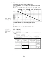
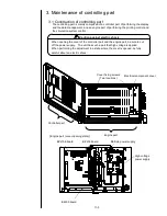


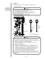
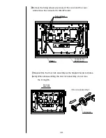
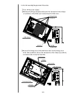

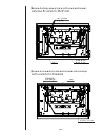


3-11
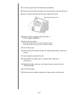
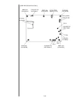
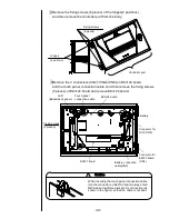
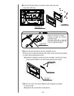
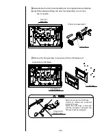
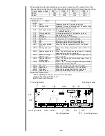
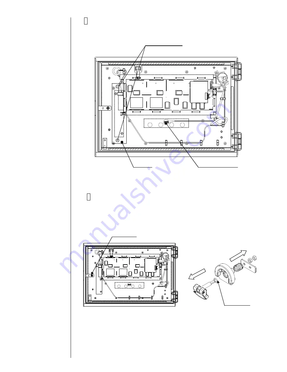
6Remove the fixing screws (2 pieces) of the cover and the cover.
and remove the connector for EZJ97 board.
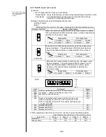
7Disassemble the door lock assembly as the diagram below indicates.
[Note] When disassembling the door lock assembly, do not lose
the O ring S6.
Door lock
assembly
【
Door lock assembly
】
O ring S6
Connector for
EZJ97 board
Cover
Cover
Fixing screws
(2pieces)
Summary of Contents for IJ PH
Page 1: ...Service Manual HITACHI Printer Model PH Revision Aug 2011 Version First edition ...
Page 2: ... Revision of PH service manual Revision Chapter Revised Page ...
Page 13: ...1 2 2 Main body internal PH D 1 8 ...
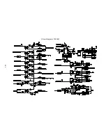
Page 80: ...3 25 3 25 Circuit diagram of EZJ95 ...
Page 201: ...7 1 7 Attached Drawing 7 1 Circulation System Diagram ...
Page 202: ...7 2 7 2 Electrical Connection Diagram ...
Page 205: ...7 5 7 4 Dimensions around charge electrode and deflection electrode Nozzle diameter 65 um ...


