


3-27
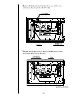
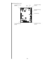
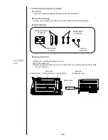
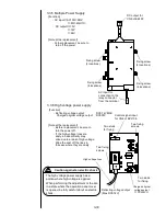
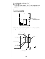
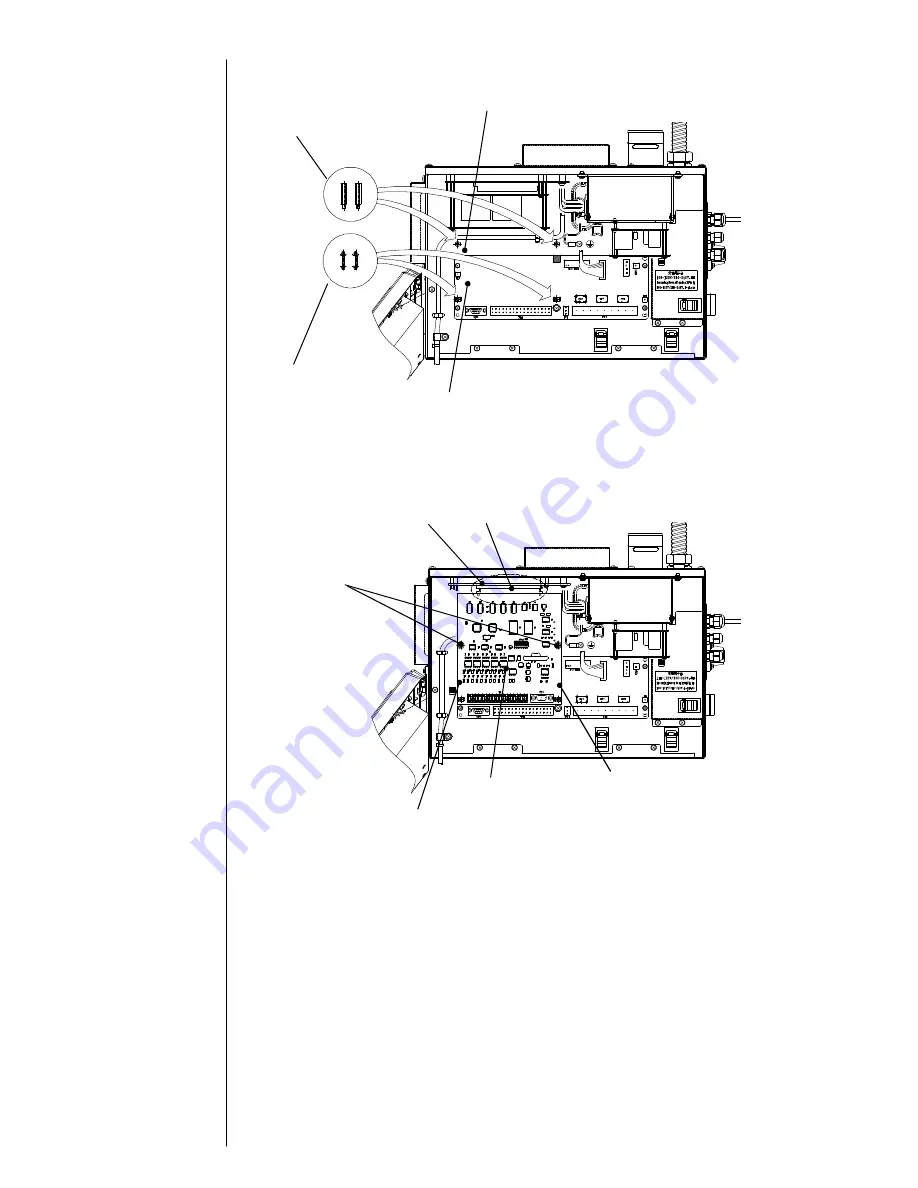
(4) Set the two hexagonal spacers to board base, and the two plastic spacers to EZJ95 board.
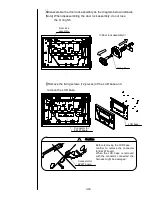
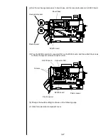
(5) Plug the EZJ99 board into connector CN1 on the EZJ93 board, and then attach the screws
to the two hexagonal screws and tighten them.
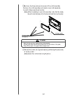
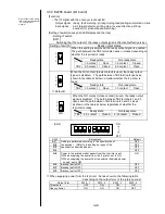
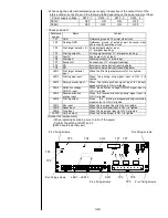
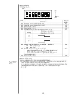
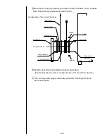
(6) Change the switch setting as shown on the following page.
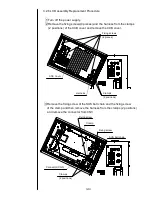
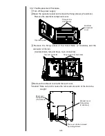
(7) Attach the electrical component cover
EZJ95 board
Hexagonal spacer
Plastic spacer
Board base
EZJ99 board
Connector CN1
EZJ93 board
Screws
Plastic spacer
Plastic spacer
Summary of Contents for IJ PH
Page 1: ...Service Manual HITACHI Printer Model PH Revision Aug 2011 Version First edition ...
Page 2: ... Revision of PH service manual Revision Chapter Revised Page ...
Page 13: ...1 2 2 Main body internal PH D 1 8 ...
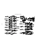
Page 80: ...3 25 3 25 Circuit diagram of EZJ95 ...
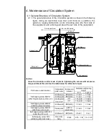
Page 201: ...7 1 7 Attached Drawing 7 1 Circulation System Diagram ...
Page 202: ...7 2 7 2 Electrical Connection Diagram ...
Page 205: ...7 5 7 4 Dimensions around charge electrode and deflection electrode Nozzle diameter 65 um ...


