3-42
3.3.14 Multiple Power Supply
[Function]
- AC input: AC100 ~ 240V (50/60Hz)
DC output: +3.4V, +5.1V, +12V, -12V, +24V
[Note at the replacement]
- In a few seconds after turned off the power, residual voltage is remaining on the parts
of multiple power supply.
- When replacing the multiple power supply, turn off the power and wait for more than
10 seconds, pull the plug out of socket, and then access the multiple power supply.
[Replacement procedure of multiple power supply]
(1) Turn off the main power and wait for more than 10 seconds.
Then pull the plug out of socket.
(2) Remove the fixing screws (6 positions) and remove the side cover.
(It is not necessary to remove the inlet base and inlet cover.)
Caution against an electric shock
In order to replace the multiple power supply, it is necessary to access inside the side
cover which has a portion where AC power is applied.
The multiple power supply has a portion where high voltage is applied. In order to avoid an
electric shock, turn off the power and wait for more than 10 seconds, pull the plug out of
socket, and then access the multiple power supply.
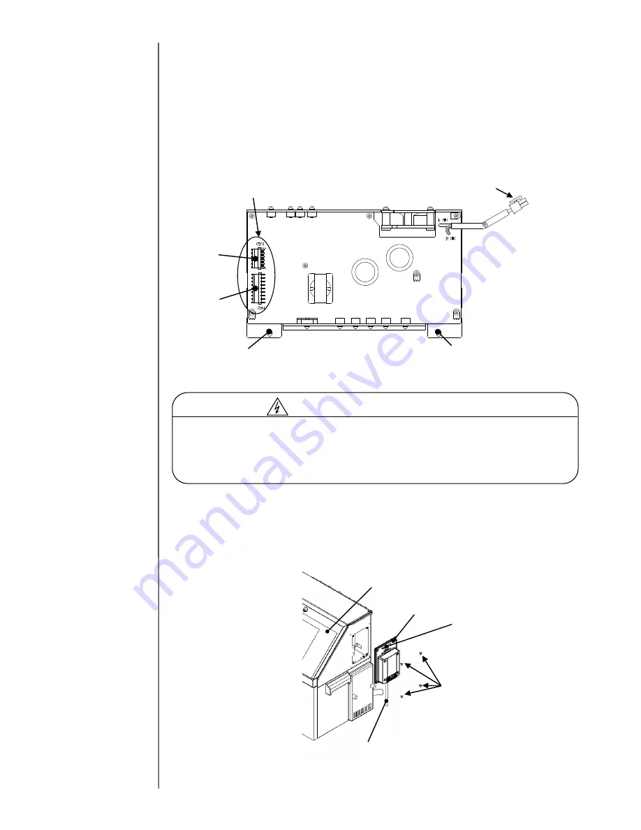
DC output for
CN2 of EZJ126 board
AC input connector (8pin)
Fixing hole of hexagonal spacer
(Two positions)
Fixing hole of hexagonal spacer
(Two positions)
CN2
CN4
Maintenance door
Side cover
Main power
switch
Four
fixing
screws
Power cord
Summary of Contents for IJ RX2
Page 1: ...Service Manual HITACHI Printer Model RX2 Revision Feb 2014 Version A ...
Page 13: ...1 8 2 External views Rear side 1 2 2 Main body internal ...
Page 14: ...1 9 1 2 3 Print head ...
Page 101: ...3 26 Circuit diagram of EZJ127A ...
Page 102: ...3 27 Circuit diagram of EZJ127B ...
Page 116: ...3 41 Circuit diagram of EZJ129 ...
Page 164: ...4 40 5 Reset the time of the R air filter to 0 on the Parts usage time management screen ...
Page 247: ...7 Attached Drawing 7 1 Circulation System Diagram Circulation System Diagram 7 1 ...
Page 249: ...7 3 7 2 2 Electrical Connection Diagram RX2 B Basic model 7 3 ...

