4-16
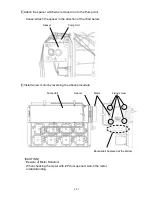
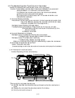
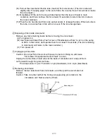
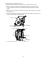
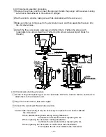
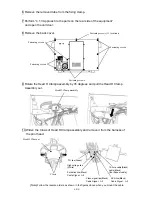
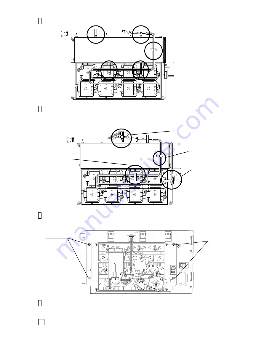
6 Remove the clamps (5 positions) that fix the wires.
7 Remove the connectors of the electric parts (15 positions) (motor,
solenoid valves(8 positions), pressure sensor, viscometer (3 positions),
level sensor and float sensor)
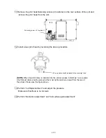
8 Remove the fixing screws at 4 positions that fix the circulation unit.
The circulation unit can be removed.
9 Clean the portion stained with ink and then install the main ink tank by
reversing the above procedure.
10
Perform “Makeup refill” and then “Ink refill”.
Make sure that any ink or makeup leak does not occur at each connecting part.
Fixing screw
Fixing screw
5 positions
1 position
8 positions
1 position
Summary of Contents for IJ RX2
Page 1: ...Service Manual HITACHI Printer Model RX2 Revision Feb 2014 Version A ...
Page 13: ...1 8 2 External views Rear side 1 2 2 Main body internal ...
Page 14: ...1 9 1 2 3 Print head ...
Page 101: ...3 26 Circuit diagram of EZJ127A ...
Page 102: ...3 27 Circuit diagram of EZJ127B ...
Page 116: ...3 41 Circuit diagram of EZJ129 ...
Page 164: ...4 40 5 Reset the time of the R air filter to 0 on the Parts usage time management screen ...
Page 247: ...7 Attached Drawing 7 1 Circulation System Diagram Circulation System Diagram 7 1 ...
Page 249: ...7 3 7 2 2 Electrical Connection Diagram RX2 B Basic model 7 3 ...


