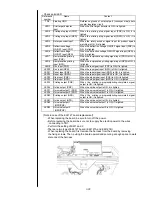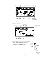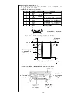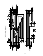
3-13
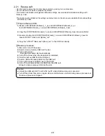
(13) Recover the data from the USB memory by using the copy data function.
(From the USB memory to the IJP)
(Note. 1) The print data are the print description, the printing specifications, the print line, the print format,
the print condition and the count condition.
(Note. 2) The unit specific data are the ink type, the nozzle diameter and the viscosity calibration data.
-
In the case where the EZJ126 board is replaced in a state allowing
NO
backup, follow the
procedure below.
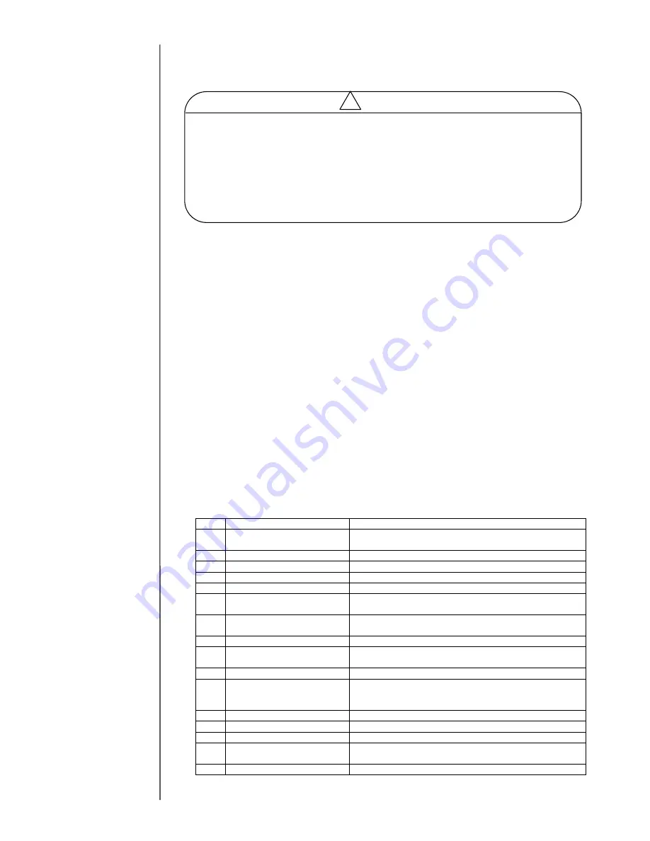
[ Replacement procedure of EZJ126 board in a state allowing NO back up]
(1) Turn off the power.
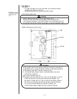
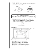
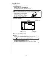
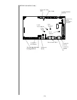
(2) Open the control panel and remove connection cable and battery on the
EZJ126 board and EZJ125 board.
(3) Remove EZJ125 board. In the event of when EZJ130 board is installed,
remove EZJ130.
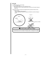
(4) Remove the cover of High voltage power supply, and then remove the EZJ126.
(5) Remove the model key from old EZJ126 board and install that key to new
EZJ126 board (CN25).
(6) Replace the EZJ126 board.
(7) Attach the cover of High voltage power supply, then attach connection cable and
battery to the EZJ126 board and EZJ125 board.
(8) Turn on the power with system data USB memory inserted.
Downloading will be performed automatically.
(9) Execute
“System reset” on the second page of the service maintenance screen.
(10
) Confirm “Serial number” on the “Unit information” screen and then confirm the
date and time.
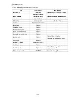
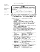
(11) Perform setup and/or adjustment according to the following table.
No.
Item
Reference manual
1
Calibrate touch screen
coordinates
Instruction manual
“7.4 Calibrating the Touch Screen coordinates”
2
Touch screen setup
Instruction manual
“6.3 Touch screen setup”
3
Selection of ink type
“2.2 System environment setup”
4
Nozzle diameter setting
“2.2 System environment setup”
5
Excitation adjustment
“2.3.1 Excitation adjustment”
6
Viscometer calibration or
Viscosity coefficient input
“2.6.1 Calibration of viscometer” or input ink viscosity
coefficient on
“2.10 Unit information”
7
Adjustment of auto phase
gain value
“2.3.4 Auto phase gain adjustment”
8
Excitation voltage setting
Service manual
“6.10 Excitation Setting Adjustment”
9
Readjustment of auto phase
gain value
“2.3.4 Auto phase gain adjustment”
10
Editing print data
Instruction manual
“4. Editing print data and printing”
11
Setting of substitution rules
Instruction manual
“4.9.3 Printing with Date/Time Changed to other
Characters (Substitution rule)
”
12
Creating a User pattern
Instruction manual
“7.3 Creating a user pattern”
13
User environment setup
Instruction manual
“6.1 Setting the user environment”
14
Setting the Date and Time
Instruction manual
“6.2 Setting a Date and Time”
15
Setting Communication
environment
Service manual
“5 Communication”
16
Setting the Password
Service manual
“3.2 Setting the password”
As for the copy data function, the user mode and the service personnel maintenance
mode are different. When replacing the EZJ126, it is necessary to back up the
unit-specific data, and so put it into the service personnel maintenance mode and then
perform the backup.
-User mode: User data (printing data (Note 1), substitution rules, user patterns)
-Service personnel maintenance mode:
User data (same as above) and unit-specific data (Note 2).
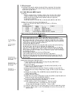
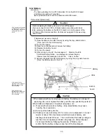
-After replacing the battery on the EZJ126 board, turn on the power of the IJP
and set the date and time. Perform set up again if it shows wrong date or time.
Caution
!
With respect to the
replacement procedure of
EZJ130, ref
er to “3.3.12
EZJ130 board
”.
With respect to the
replacement procedure of
EZJ125, ref
er to “3.3.6
EZJ125 board
”.
As for the Unit
Information, see
“2.10
Unit information
”.
As for the System
reset, see
“2.8 System
reset
”.
Summary of Contents for IJ RX2
Page 1: ...Service Manual HITACHI Printer Model RX2 Revision Feb 2014 Version A ...
Page 13: ...1 8 2 External views Rear side 1 2 2 Main body internal ...
Page 14: ...1 9 1 2 3 Print head ...
Page 101: ...3 26 Circuit diagram of EZJ127A ...
Page 102: ...3 27 Circuit diagram of EZJ127B ...
Page 116: ...3 41 Circuit diagram of EZJ129 ...
Page 164: ...4 40 5 Reset the time of the R air filter to 0 on the Parts usage time management screen ...
Page 247: ...7 Attached Drawing 7 1 Circulation System Diagram Circulation System Diagram 7 1 ...
Page 249: ...7 3 7 2 2 Electrical Connection Diagram RX2 B Basic model 7 3 ...

