KH-WS1
– 13 –
3
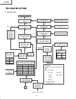
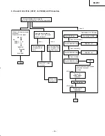
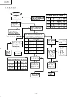
When the operation malfunctions after receiving operation starts
Start
No
or
or
or
or
WS SAT
NO BEAM
or
or
etc.
"SEARCH"
No
Yes
Yes
Yes
No
No
No
No
No
No
No
"SEARCH"
Display of part
on LCD:
Continue blinking
of "SEARCH"
Receiving
operation
Is the oscillator circuit of
IC102
- and
-pin in
operation?
Can I2C bus line connected from
IC101
- and
-pin to all ICs
operate? (80 pin nos.
and
)
Are IC101
-pin and IC102
-pin in "H"?
Is every port connected from
IC101
-pin to IC102 and
IC103 in "H"?
Check the circuits connected to
each IC terminals, the patterns
and the soldered parts, the
concerned IC may malfunction.
Is the synchronous pulse "H L"
repeated at IC103
-pin?
Does IC103
-pin operate
in "L"?
Check around the
terminals of IC103
and IC101.
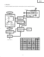
When the stations receivable with other units can not be received though the operation is proper
Execute "SEEK" Search.
Push MODE and BEAM SEEK keys.
Can IC101
-pin switch "H to L"
after starting SEEK until it ends?
(80 pin:
)
Check IC101.
Check IC105 and
IC106.
Check the output line of
IC105 and IC106, and
around the terminals of RF101.
Does the voltage for RF101 (Tuner)
-pin
change from 3 V to 2.4 V when SEEK
search until it ends?
Is there voltage output between the center pin
and the ground of the antenna jack on the unit
when the antenna is disconnected?
Does the voltage change from 3 V to 2.4 V
when SEEK search until it ends?
Check the output line of
IC105 and IC106, and
around the terminals of RF101.
4
When the stations receivable with other units can not be received though the operation is proper
KH/Pg 10-17 (TroubleSht)
10/11/00, 1:50 PM
13
Summary of Contents for KHWS1W
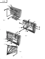
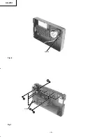
Page 5: ...KH WS1 5 Fig 4 Fig 5 5 6 ...
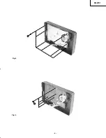
Page 6: ...KH WS1 6 Fig 6 Fig 7 metal pin 7 8 Connector J 9 ...
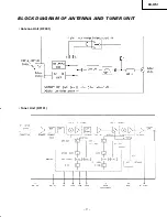
Page 17: ...KH WS1 17 BLOCK DIAGRAM OF ANTENNA AND TUNER UNIT Antenna Unit RF001 Tuner Unit RF101 ...
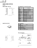
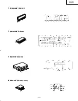
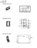
Page 26: ...KH WS1 26 TA7368P IC206 207 BU4066BCF IC204 BA033ST V5 IC209 1 9 7 8 1 14 1 2 3 4 5 ...
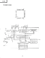
Page 28: ...KH WS1 28 TC9298F IC302 ...
Page 32: ...KH WS1 32 SATELLITE P W B TUNER PWB Soldering Side Soldering Side ...
Page 33: ...KH WS1 33 Component Side TUNER PWB SATELLITE P W B Component Side ...
Page 34: ...KH WS1 34 Soldering Side MAIN PWB ...
Page 35: ...KH WS1 35 MAIN P W B Component Side ...
Page 37: ...KH WS1 CIRCUIT DIAGRAM TUNER DTS Circuit 38 37 it A2 10 11 00 1 57 PM 37 ...
Page 38: ...CIRCUIT DIAGRAM ATELLITE Circuit 40 39 it A2 10 11 00 1 57 PM 38 ...
Page 39: ...KH WS1 42 41 BLOCK DIAGRAM Lk Xploded A3 10 11 00 2 00 PM 41 ...
Page 41: ...THE UPDATED PARTS LIST FOR THIS MODEL IS AVAILABLE ON ESTA ...


