Orientation to Inverter Features
In
v
e
rt
er Mounting
and Installation
2–4
3. Third-level access
- First, ensure no power
source of any kind is connected to the
inverter. If power has been connected, wait
five minutes after powerdown and verify
the Power LED is OFF to proceed. Then
locate the recessed retention screw on the
left side main front panel (it is along the
left hinge area on some models, or behind
the first access door on others). Use a small
screwdriver (Regular or Phillips) to loosen
the screw. Swing the door around to the
right to reveal the internal components of
the drive. The two-level tiered 12-position
terminal block accepts wires for the power
input and wires to the motor.
Notice the housing partition that lifts out to
allow full access to the terminals for wiring as
shown. Never operate the inverter drive with
the partition removed or the full access door
opened.
The alarm circuit connections are accessible
on the 3-position connector near the modular
connector on the rear of the main panel door.
The nearby relay provides both normally-
open and normally-closed logic for interface
to an external alarm. The alarm circuit may
carry hazardous live voltages even when the
main power to the inverter is OFF. So, never
directly touch any terminal or circuit compo-
nent. A notch in the removable partition
serves as the exit path for alarm circuit wiring.
The following sections will describe the
system design and guide you through a
step-by-step installation process. After the
section on wiring, this chapter will show
how to use the front panel keys to access
functions and edit parameters.
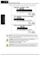
Retention screw
Housing partition
Alarm
connector
Power and motor
connector terminals


