background image

Addendum Number: NB642X
Addendum for Manual: NB576X

L100DN
DeviceNet


Series Inverters

In This Addendum....

page

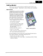
— Getting Started ................................................. 3
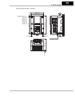
— Inverter Mounting and Installation .................... 9
— Configuring Drive Parameters........................ 26
— Operations and Monitoring............................. 31
— Network Control and Monitoring..................... 39
— Troubleshooting and Maintenance ................. 70

In the Appendices:

— DeviceNet Object Lists ................................... 71
— Network Register Map.................................... 78
— Drive Parameter Settings Tables.................... 88
— Restoring Factory Default Settings ................ 94

Addendum to L100 Series 
Inverter Instruction Manual

READ THIS FIRST!

Summary of Contents for L100DN DeviceNet Series Addendum

Page 1: ...tallation 9 Configuring Drive Parameters 26 Operations and Monitoring 31 Network Control and Monitoring 39 Troubleshooting and Maintenance 70 In the Appendices DeviceNet Object Lists 71 Network Register Map 78 Drive Parameter Settings Tables 88 Restoring Factory Default Settings 94 Addendum to L100 Series Inverter Instruction Manual READ THIS FIRST ...

Page 2: ...2 Revisions DeviceNet is a trademark of Open DeviceNet Vendor Association Inc Revision History Table No Revision Comments Date of Issue Addendum No Initial Release of Addendum NB642X Jan 2003 NB642X ...

Page 3: ...rter can also connect to a DeviceNet network for control and monitoring The main features are 200V and 400V Class inverters UL or CE version available Convenient keypad for parameter settings Built in DeviceNet network interface to allow control and monitoring via a DeviceNet network Sixteen programmable speed levels Three wire control interface Up Down electronic motorized speed pot function Two ...

Page 4: ...r output freq Front panel LEDs for networking MS Module Status LED NS Network Status LED Front panel door Half door for programming keys and control terminals Analog input terminals H O OI L PWM output terminal FM Intelligent input terminals 1 2 3 4 5 1 2 3 only Intelligent input functions Includes AT Includes STA STP F R UP DWN DNT OPE Intelligent output terminals 11 12 AL0 to AL2 11 12 only Inte...

Page 5: ...below Inverter model number Motor capacity for this model Output Rating Frequency voltage current Manufacturing codes Lot number date etc Specifications label Regulatory agency approvals Power Input Rating frequency voltage phase current L100DN 002 H F U Restricted distribution E Europe U USA Input voltage N single or three phase 200V class H three phase 400V class L three phase only 200V class Ap...

Page 6: ...k supports up to 64 devices each with their own node address One device will be the network master all other device s will be network slaves The L100DN inverter will operate as a network slave as the network master also called host computer will send commands to the slaves A factory network such as DeviceNet allows you to integrate devices of many different types even from various manufacturers al...

Page 7: ...O continuous update of output frequency FWD REV Run Operator panel Run Stop Forward Reverse run change by command External signal Forward run stop Reverse run stop on intelligent terminals Network Forward run stop Reverse run stop Intelligent input terminal FW forward run command RV reverse run command CF1 CF4 multi stage speed setting JG jog command 2CH 2 stage accel decel command FRS free run st...

Page 8: ...orage temperature refers to the short term temperature during transport Note 5 Conforms to the test method specified in JIS C0911 1984 For the model types excluded in the standard specifications contact your Hitachi sales repre sentative Operat ing Environ ment Temperature Operating ambient 10 to 50 C 3 Storage 25 to 70 C 4 Humidity 20 to 90 humidity non condensing Vibration 5 5 9 m s2 0 6G 10 to ...

Page 9: ...for consistent ease of use The inverter construction has a heat sink at the back of the housing The larger models include a fan s to enhance heat sink perfor mance The mounting holes are pre drilled in the heat sink for your convenience Never touch the heat sink during or just after operation it can be very hot The electronics housing and front panel are built onto the front of the heat sink The f...

Page 10: ...down and verify the Power LED is OFF to proceed Then locate the recessed retention screw on the left side main front panel it is along the left hinge area on some models or behind the first access door on others Use a small screwdriver Regular or Phillips to loosen the screw Swing the door around to the right to reveal the internal components of the drive The two level tiered 12 position terminal ...

Page 11: ...any terminal or circuit component This protects you from touching a n unexpected live circuit and it protects the inverter from electrostatic discharge ESD The power and motor connector terminals are accessible with the removal of the housing partition The input power and motor connec tions use the lower row of terminals The upper row is for connecting dynamic braking components Housing partition ...

Page 12: ...stall your L100DN DeviceNet inverter is in the standard manual with the exception of the dimension drawings which follow below NOTE After doing the basic installation physical mounting and power wiring per the instructions in Chapter 2 of the L100 manual be sure to return to this addendum for the Powerup Test and Front Panel Keypad orientation Check Inverter Dimensions Locate the applicable drawin...

Page 13: ... 39 5 0 20 5 0 20 130 5 12 110 4 33 129 5 08 2 5 0 10 L100DN 004HFE2 004HFU2 011NFE2 007NFE2 007NFU2 MODEL Ground Terminal 98 3 86 118 4 65 130 5 12 110 4 33 5 0 20 5 0 20 156 6 14 6 6 24 L100DN 007HFE2 no fan 007HFU2 no fan 015HFE2 015HFU2 022HFE2 022HFU2 Ground Terminal ...

Page 14: ...al drawings continued L100DN 015NFE2 128 5 04 168 6 61 5 0 20 140 5 51 180 7 09 10 0 39 153 6 02 6 0 24 015NFU2 Ground Terminal 140 5 51 168 6 61 128 5 04 180 7 09 164 6 46 5 0 20 5 0 20 L100DN 022NFE2 022NFU2 037LFU2 030HFE2 040HFE2 040HFU2 6 0 24 ...

Page 15: ...L100DN Inverter 15 Dimensional drawings continued 182 7 17 236 9 29 160 6 30 257 10 12 7 0 28 7 0 28 170 6 69 6 0 24 055LFU2 075LFU2 055HFE2 055HFU2 075HFE2 L100DN 075HFU2 1 0 04 Ground Terminal ...

Page 16: ...e inverter and motor are generally compatible 3 Give a brief introduction to the use of the built in operator keypad The powerup test gives you an important starting point to ensure a safe and successful application of the Hitachi inverter We highly recommend performing this test before proceeding to the other chapters in this manual Pre test and Operational Precautions The following instructions ...

Page 17: ...If you have followed all the steps cautions and warnings up to this point you re ready to apply power After doing so the following events should occur The POWER LED will illuminate The numeric 7 segment LEDs will display a test pattern then stop at 0 0 The Hz LED will be ON This assumes the inverter is in Monitor Mode and is displaying D_01 the output frequency The MS Module Status and NS Network ...

Page 18: ...a Run FWD or Run REV command Stop Reset Key Press this key to stop the motor when it is running uses the programmed deceleration rate This key will also reset an alarm that has tripped Module Status LED ON green when the inverter has power The Module Status LED may also be flashing and or red in color For a description of all LED states and their meanings see the table in Step 6 Monitor Test Verif...

Page 19: ...Hz To edit the parameter the inverter must be in Program Mode PGM LED will be ON You use the front panel keys to first select the function code A_04 After displaying the value for A_04 use the Up Down or keys to edit it NOTE The inverter 7 segment display shows lower case b and d meaning the same as the upper case letters B and D used in this manual for uniformity A to F The inverter automatically...

Page 20: ... 4 digit display and a few keys and LEDs So it is important to become familiar with the basic navigational map of parameters and functions in the diagram below 1 2 2 1 Edit Write data to EEPROM Increment decrement value 2 1 2 1 2 1 2 1 2 1 1 Select Parameter Select Function or Group Display Data 2 Return to parameter list 2 1 2 1 2 1 2 1 2 1 2 1 Edit Parameter FUNC FUNC FUNC FUNC FUNC STR 000 0 d ...

Page 21: ...ate the motor at elevated frequencies after getting their approval Otherwise there is the danger of equipment damage Setting the Motor Base Frequency The motor is designed to operate at a specific AC frequency Most commercial motors are designed for 50 60 Hz operation First check the motor specifications Then follow the steps in the table below to verify the setting or correct for your motor DO NO...

Page 22: ...he table resumes action from the end of the previous table NOTE When you press the STR key in the last step above and the display 02 the Run Key Enable LED above the RUN key on the keypad will turn ON This is normal and does not mean the motor is trying to run It means that the RUN key is now enabled DO NOT press the RUN key at this time finish out the programming exercise first Action Display Fun...

Page 23: ... Control and Monitoring on page 39 This step in the powerup test will set F_01 Output Frequency Setting to 15Hz CAUTION Be sure to set F_01 Output Frequency Setting to a safe value for your motor and application The step below only uses 15Hz as an example This step concludes the parameter setups for the inverter You are almost ready to run the motor for the first time TIP If you became lost during...

Page 24: ... is no longer in programming mode even while you are selecting the particular monitoring parameter After pressing the Function key the display shows the current speed is zero at this point Running the Motor If you have programmed all the parameters up to this point you re ready to run the motor First review this checklist 1 DO NOT connect the inverter to the DeviceNet network or supply 24V network...

Page 25: ...le Use the following formula to calculate the RPM The theoretical speed for the motor is 1800 RPM speed of torque vector rotation However the motor cannot generate torque unless its shaft turns at a slightly different speed This difference is called slip So it s common to see a rated speed of approxi mately 1750 RPM on a 60 Hz 4 pole motor Using a tachometer to measure shaft speed you can see the ...

Page 26: ...04 C_05 C_06 C_14 C_15 C_16 Intelligent output terminal settings for 4 to 6 C_23 FM signal selection C_33 Intelligent output terminal settings for AL0 to AL2 New intelligent input terminal functions not present in standard L100 STA Start Motor option code 20 STP Stop Motor option code 21 F R Forward Reverse option code 22 DNT Select DeviceNet option code 25 UP Remote control Up function option cod...

Page 27: ...cription FE CE FU UL F Jpn Units C_01 Terminal 1 function Select function for terminal 1 20 options see inverter manual 00 FW 00 FW 00 FW C_02 Terminal 2 function Select function for terminal 2 20 options see inverter manual 21 STP 21 STP 21 STP C_03 Terminal 3 function Select function for terminal 3 21 options see inverter manual and Note below 12 EXT 12 EXT 12 EXT C Function Run Mode Edit Defaul...

Page 28: ...tary contact uses acceleration profile OFF No change to motor operation 21 STP Stop Motor ON Stop motor rotation on momentary contact uses deceleration profile OFF No change to motor operation 22 F R FWD REV ON Select reverse direction of rotation OFF Select forward direction of rotation 25 DNT DeviceNet Select ON Inverter operates under DeviceNet network control OFF Inverter operates under local ...

Page 29: ...normally closed active high for these terminals in order to invert the sense of the logic C Function Run Mode Edit Defaults Func Code Name Description FE CE FU UL F Jpn Units C_21 Terminal 11 function Select function for terminal 11 5 options see inverter manual 00 RUN 00 RUN 00 RUN C_22 Terminal 12 function Select function for terminal 12 5 options see inverter manual 05 AL 05 AL 05 AL C Function...

Page 30: ...63 63 P_43 DeviceNet control enable Two options select codes 00 Disable 01 Enable 01 01 01 P_44 DeviceNet comm watchdog timer Range is 0 00 to 99 99 seconds 1 00 1 00 1 00 P_45 Inverter action on DeviceNet comm error Five options 00 Trip 01 Decelerate and trip 02 Hold last speed 03 Free run stop 04 Decelerate and stop 01 01 01 P_46 DeviceNet polled I O Output instance number Three settings 20 21 1...

Page 31: ...n detail in Step 2 Connect Network Devices on page 43 12 11 1 2 3 L D CL V CM2 L100DN P24 Open collector outputs CANbus High Power source 3 phase or 1 phase per inverter model R L1 S L2 T N L3 U T1 V T2 W T3 Motor FW STP Intelligent inputs 3 terminals CANbus Low Drain NOTE For the wir ing of intelligent I O be sure to use twisted pair shielded cable Attach the shield wire for each signal to its re...

Page 32: ...iceNet connector signals must meet the electrical requirements given by the DeviceNet industry standards For more information visit the Open DeviceNet Vendor Association website at http www odva org Logic inputs Logic outputs L 3 1 2 P24 CM2 12 11 DeviceNet network connector Auxiliary network power connector Terminal Name Description Ratings P24 24VDC for logic inputs 24VDC 30 mA max Notes Do not ...

Page 33: ...t the operation command selection A_02 01 for input terminal control of motor If you have a motor control interface that needs logic level control rather than momentary pulse control use the FW and RV inputs instead Option Code Terminal Symbol Function Name Input State Description 20 STA Start Motor ON Start motor rotation on momentary contact uses acceleration profile OFF No change to motor opera...

Page 34: ...dge sensi tive input an OFF to ON transition gives the Start command The control of direction is level sensitive and the direction may be changed at any time STP Stop Motor is also a level sensitive input and the Stop signal has priority over the Start signal When both STA and STP signals are ON the STP signal has priority motor output will be OFF However the motor output resumes after STP signal ...

Page 35: ...rovide a dedicated Stop signal input as shown below In the graph below the network FWD command places the inverter in Run mode While the motor is running the local STP input terminal activates causing the inverter to decelerate the motor to a stop It remains stopped even though the FW command is still active The FW command must turn OFF and ON again to resume motor operation Inverter Network host ...

Page 36: ...iguration see Step 2 Connect Network Devices on page 43 Option Code Terminal Symbol Function Name State Description 25 DNT DeviceNet Select ON The inverter operates per commands and param eters output freq accel decel from DeviceNet OFF The inverter operates per local commands keypad or terminal Run Stop and its internal parameters speed accel decel Valid for inputs C_01 C_02 C_03 Required setting...

Page 37: ...ency responds to the UP and DWN commands Output Frequency UP DWN FW or RV t Option Code Terminal Symbol Function Name Input State Description 27 UP Remote Control UP Function ON Accelerates increases output frequency motor from current frequency OFF Output to motor operates normally 28 DWN Remote Control DOWN Function ON Decelerates decreases output frequency motor from current frequency OFF Outpu...

Page 38: ... ON Forces the operator interface Run command to over ride commands from input terminals such as FW RV OFF Run command operates normally as configured by A_02 Valid for inputs C_01 C_02 C_03 Required settings A_02 01 Notes When the OPE signal is ON the keypad Run and Stop keys are active and FW or RV signal is ignored However OPE cannot cause the keypad to over ride the DeviceNet host commands To ...

Page 39: ...ons and device power are in the same cable power devices such as motor drives still require a main power source Devices may be connected or disconnected without powering down the network if daisy chained Flexible device definitions the device protocol provides for many types of input and output structures Open standard allows multiple vendors to produce many types of products that can coexist on a...

Page 40: ...ure not to skip any steps in this section NOTE Be sure to install the inverter and perform the powerup test described in the Inverter Mounting and Installation on page 9 before attempting network operation The step to DeviceNet network control and monitoring are 1 Design your network layout 2 Connect network devices a Add network termination b Add network power 3 Prepare network host computer 4 Pr...

Page 41: ... MAC ID Media Access Control Identification As shown in the diagram the node addresses do not have to occur in a particular sequence in the physical layout Showing node connections now in greater detail the connection to each device in the middle of the network may be a daisy chain connection or a drop connection The differ ence is that a daisy chain connection enters and exits right at the connec...

Page 42: ...lowing table NOTE If thin cable is used for the trunk line the maximum distance is 100m for all baud rates Baud Rate Trunk length thick cable Drop Length Maximum Cumulative 125 kbps 500m 1640 ft 6m 20 ft 156m 512 ft 250 kbps 250m 820 ft 6m 20 ft 78m 256 ft 500 kbps 100m 328 ft 6m 20 ft 39m 128 ft ...

Page 43: ...tion resistor as several such devices together would overload a network The terminations provides signal integrity and noise immunity Therefore add two resistors as close to the endpoint connectors as possible TIP To simplify configuration and startup we recommend starting with just the network host PLC or computer and the inverter It is easier to resolve addressing or other conflicts with fewer d...

Page 44: ...a result DeviceNet specifications support up to 8A per network segment NOTE Class II NEC Code limits the current for any network segment to 4A DeviceNet thick type cable is limited to 8A thin type cable is limited to 3A Add a 24VDC supply to the network as shown below It is not necessary to power it for this step later steps will provide powerup instructions Alternatively you can use the auxiliary...

Page 45: ...e two connectors to ensure the polarity is maintained The power supply must provide proper output current limit and fusing for the network device load Remember that you must open the front door panel of the inverter to connect or disconnect wiring to the auxiliary network power connector If power has been connected wait five minutes after powerdown and verify the Power LED is OFF before opening th...

Page 46: ... Visit the website at http www odva org Navigate to the Downloads area and then to EDS files From the EDS files select Hitachi as the manufacturer Download the file that matches your inverter s version L100DN2 for example Then load or place the EDS file in your network host device in the location directory it requires for use in network device scanning Refer to the documentation of your host devic...

Page 47: ...lts Func Code Name Description P_41 DeviceNet baud rate Three options select codes 00 125 kbps 01 250 kbps 02 500 kbps 00 P_42 DeviceNet MAC ID Selects the DeviceNet node address range is 0 to 63 63 P_43 DeviceNet control enable Two options select codes 00 Disable 01 Enable 01 P_44 DeviceNet comm watchdog timer Range is 0 00 to 99 99 seconds 1 00 P_45 Inverter action on DeviceNet comm error Five o...

Page 48: ...t supported in L100DN These master commands are oriented to simpler I O devices time based updates or value change updates More suited to simple or analog applications such as data logging these network master commands are not supported by L100DN inverters Explicit Messaging supported in L100DN The Explicit Messaging mechanism goes beyond the four standard scan mechanisms listed above A master can...

Page 49: ... O Configurations on page 66 The following table defines individual bits of the status byte Inverter Produced Data Host Input Instance P_47 101 Byte Bit 7 Bit 6 Bit 5 Bit 4 Bit 3 Bit 2 Bit 1 Bit 0 0 Input term 3 Input term 2 Input term 1 Freq Arrival Trip RV Run FW Run 1 Inverter status see status code table next page 2 Output frequency monitor low byte D_01 value 3 Output frequency monitor high b...

Page 50: ... The inverter is in Run Mode 2 The inverter is in Jog Mode 3 The inverter is in Stop Mode and the motor output is free running coasting 4 The inverter is executing DC braking includes CD braking wait time 5 The inverter is attempting a restart with frequency matching B_01 03 6 The output is stopped for an instantaneous power failure 7 The inverter is attempting a restart with frequency matching B_...

Page 51: ... OFF and ON The table below shows how to interpret the status LED indications At this point the correct status is MS green NS OFF LED Color Status Corrective Action MS Green Normal power ON status Flashing Green Inverter in standby state Red Fatal error trip E11 or E12 Confirm electrical noise level is acceptable Replace inverter Flashing Red Trip condition non fatal Look up error code in manual C...

Page 52: ...r s MS LED Green and now the NS LED Green NOTE If the NS LED OFF the network is disconnected Check the cable and also check the host application software settings If the NS LED Flashing Green the network is connected but idle Start the host network scan to cause NS LED Green If Red or Flashing Red use the Status LED table on the previous page to troubleshoot h Confirm that the host computer can se...

Page 53: ...t corresponds to 1 1A D_02 reading when the scale factor of 10 is applied This value represents a small inverter and motor size your reading may differ Word 3 The decimal value of 0 for trip code D_08 reading corresponds to no trip status NOTE When a trip event occurs the polled I O will indicate it by Trip Bit 1 in Word 0 and the actual Trip Code in Word 3 When the trip condition is cleared Stop ...

Page 54: ...s via a DeviceNet connection A DeviceNet setting or signal at the inverter enables or permits network control This means that an operator or control system at the inverter can at any time take back control of the inverter from a network host by disabling DeviceNet control The inverter uses P_43 DeviceNet Control Enable for the primary method of control selection By default P_43 1 set to enable net...

Page 55: ...table below describes the Network Control and Network Reference setting logic The logic requires that the inverter has enabled DeviceNet control as described above Note 1 Logic above requires inverter s P_43 or DNT to enable DeviceNet control Typically a network host computer needs to have control of Run Stop speed accel and decel This corresponds to No 3 above where both Network Control and Netwo...

Page 56: ... bits of the control byte Inverter Consumed Data Host Output Instance P_46 100 Byte Bit 7 Bit 6 Bit 5 Bit 4 Bit 3 Bit 2 Bit 1 Bit 0 0 Network Refer ence Network Control Free run Stop Fault Reset RV Run FW Run 1 2 Output frequency low byte host override for F_01 value 3 Output frequency high byte host override for F_01 value 4 Acceleration time low byte host override for F_02 value 5 Acceleration t...

Page 57: ...the inverter turns OFF This indicates that the inverter has switched its control source from local to network control e Turn ON the FW Run bit bit 0 in Word 0 as shown below The motor will now begin to run The output frequency will be 15 00Hz set by F_01 To verify the motor speed monitor D_01 on the inverter display or use the host computer to observe the actual output frequency reported in the po...

Page 58: ...output data should match the values below NOTE The scaling of the polled I O data for output frequency accel decel values corresponds to the network scale factors for parameters F_01 F_02 and F_03 respec tively A listing of inverter parameters and scale factors is in the Network Register Map on page 78 d Turn ON the FW Run bit bit 1 in Word 0 as shown below The motor will now begin to run The outp...

Page 59: ...pplication may require stopping the motor suddenly in certain conditions to avoid injury to personnel or equipment damage If so be sure to configure the STP input terminal on the inverter described in Three wire Interface Operation on page 33 This will provide a way for the control environment at the inverter to stop the motor should the host computer fail to turn the motor OFF when required MSB L...

Page 60: ... ignored When an intelligent input terminal CF1 CF2 CF3 CF4 JG or 2CH turns ON the inverter performs the related function with priority If the inverter reset is ON at powerup a communication time out error will occur at the master In this case the master will need to re establish communications When an inverter has a power cycle or reset the DeviceNet master may request to start or resume motor ro...

Page 61: ...llowing table A particular inverter on the network has a specific node address default 63 To access a particular parameter in that inverter the host computer uses the class instance and attribute numbers together The address ranges indicated in the table above could access any one of thousands of values within a device if needed In DeviceNet terminology a read access is called get and a write acce...

Page 62: ...display data format hex or decimal of the response if your host application provides this e Have the host computer send the explicit message f Verify the inverter s response is 5DCh or 1500 decimal If not check the values in the get attribute request and check the present value of parameter F_01 at the inverter g Apply the scale factor in the Network Register Map table For F_01 divide by 100 so 15...

Page 63: ...t to 10 0 seconds The figure below shows the velocity profile for the example program It consists of a forward rotation followed by a reverse rotation The program will send the commands and parameter values to set the speed and accel decel values Command Bit Sequencing The order of 0 to 1 transitions of the host computer s Word 0 command bits is important First set the Network Control bit bit 5 an...

Page 64: ... FW Run bit 0 Wait 20 seconds Set output frequency 15 0 Hz Set accel decel times 20 sec Set RV Run bit 1 Wait 15 seconds Set RV Run bit 0 Freq Arrival 0 Run Mode 0 FW Run 0 RV Run 0 Freq monitor 0 00Hz Current monitor 0 0A Trip code 0 Freq Arrival 1 Run Mode 1 FW Run 1 RV Run 0 Freq monitor 25 0Hz Current monitor 1 1A Trip code 0 Freq Arrival 1 Run Mode 1 FW Run 1 RV Run 0 Freq monitor 10 00Hz Cur...

Page 65: ...0h 0000h 8 RV run 0062h 15 Hz 15 00 05DCh 20 sec 00C8h Accel stage 0102h xxxxh 9 Constant speed 0112h 05DCh 10 Stop 0060h same same Decel stage 0102h xxxxh 11 Stop 0000h 0000h 9 10 11 6 7 1 2 3 4 5 8 Host output hex Word 0 Word 1 Word 2 Word 3 Program Example With Data Forward rotation Reverse rotation 0060 09C4 0064 0064 freq 25Hz freq 10Hz freq 15Hz accel decel 10sec accel decel 20sec 0061 09C4 ...

Page 66: ...W Run 1 2 Output frequency low byte host override for F_01 value 3 Output frequency high byte host override for F_01 value Inverter Consumed Data Host Output Instance P_46 21 Byte Bit 7 Bit 6 Bit 5 Bit 4 Bit 3 Bit 2 Bit 1 Bit 0 0 Network Refer ence Network Control Fault Reset RV Run FW Run 1 2 Output frequency low byte host override for F_01 value 3 Output frequency high byte host override for F_0...

Page 67: ...tor to free run coast and stop 4 5 Network Control Run Stop control is local to inverter Run Stop control is from network host polled I O 6 Network Reference Output freq accel decel is from F_01 F_02 F_03 Output freq accel decel is from network host polled I O 7 Inverter Produced Data Host Input Instance P_47 70 Byte Bit 7 Bit 6 Bit 5 Bit 4 Bit 3 Bit 2 Bit 1 Bit 0 0 FW Run Trip 1 Inverter status s...

Page 68: ...W Inverter in RV Run 4 Ready Inverter is not ready Inverter is ready status byte code 3 4 or 5 5 Network Control Run Stop control is local to inverter Run Stop control is from network host polled I O 6 Network Reference Output freq accel decel is from F_01 F_02 F_03 Output freq accel decel is from network host polled I O 7 Frequency Arrival Inverter stopped or in accel or decel Inverter output arr...

Page 69: ...d Data Inverter State Code Byte Code dec Description 0 The inverter is Stop Mode 1 The inverter is in Run Mode 2 The inverter is in Jog Mode 3 The inverter is in Stop Mode and the motor output is free running coasting 4 The inverter is executing DC braking includes CD braking wait time 5 The inverter is attempting a restart with frequency matching B_01 03 6 The output is stopped for an instantaneo...

Page 70: ...e signal is ON at the intelli gent input terminal DNT if assigned DNT input has priority over P_43 Note 4 The DeviceNet connection time out refers to the time out within the DeviceNet Connection Object per the DeviceNet specifications In if Run Mode when the time out occurs the inverter decelerates the motor to a stop Note 5 The host computer can release the connection to the inverter via the stan...

Page 71: ...I Release 2 0 Volume II Release 2 0 Vendor name Hitachi Ltd Vendor ID 74 Device profile name AC Drive Profile number 2 Product catalog number Product revision 3 1 Physical conformance data Network power consumption 50mA at 11VDC Connector style Open pluggable Isolated physical layer Yes LEDs supported Module Status LED Network Status LED Default MAC ID 63 Baud rate selection Software selectable Ba...

Page 72: ...ned double integer Int 4 Bytes 0 232 1 SINT Signed short integer Int 1 Byte 128 127 INT Signed integer Int 2 Bytes 32768 32767 DINT Signed double integer Int 4 Bytes 231 231 1 Identity Object Class ID 1 hex Category Attribute ID Access Rule Data Type Initialization Class not supported Instance 1 Vendor ID 1 Get UINT 74 Device type 2 Get UINT 2 AC drive Product code 3 Get UINT L100DN2 0702h Major r...

Page 73: ...start frequency setting Invalid parameter check F_01 A_03 A_20 A_35 A_38 A_52 A_61 A_62 20h 00 Value less than lower frequency limit setting 01 Value more than upper frequency limit setting 02 Value more than maximum frequency setting 03 Out of range condition not listed above Invalid parameter 04 DeviceNet Object Class ID 3 hex Category Attribute ID Access Rule Data Type Initialization Class Revi...

Page 74: ...Connection Object Class ID 5 hex Category Attribute ID Access Rule Data Type Initialization Class not supported Instance 1 State 1 Get USINT Instance type 2 Get USINT 00 Transport class trigger 3 Get BYTE 83h Produced connection ID 4 Get UINT Consumed connection ID 5 Get UINT Initial comm characteristics 6 Get BYTE 21h Produced connection size 7 Get UINT C8h Consumed connection size 8 Get UINT C8h...

Page 75: ...Get UINT 08h Expected packet rate 9 Get Set UINT 03E8h Watchdog time out action 12 Get Set USINT 0 Produced conn path length 13 Get UINT 3 Produced connection path 14 Get UINT array 623625 Consumed conn path length 15 Get UINT 3 Consumed connection path 16 Get UINT array 623624 Supported Services Connection Object Service Name Code Description Reset 05h Get_Attribute_Single 0Eh Set_Attribute_Singl...

Page 76: ...gle 0Eh Set_Attribute_Single 10h Control Supervisor Object Class ID 29 hex Category Attribute ID Access Rule Data Type Initialization Class Revision 1 Get WORD 0001 Instance 1 Run1 3 Get Set BYTE 00 Run2 4 Get Set BYTE 00 Network Control 5 Get Set BYTE 00 State 6 Get BYTE Running1 7 Get BYTE 00 Running2 8 Get BYTE 00 Ready 9 Get BYTE 00 Faulted 10 Get BYTE 00 Warning 11 Get BYTE 00 Fault reset 12 ...

Page 77: ... 8 Get Set WORD F_01 setting Current actual 9 Get WORD 0000 Current limit 10 Get Set WORD B_21 setting Input voltage 16 Get WORD Output voltage 17 Get WORD 0000 Accel time 18 Get Set WORD F_02 setting Decel time 19 Get Set WORD F_03 setting Low speed limit 20 Get Set WORD A_62 setting High speed limit 21 Get Set WORD A_04 setting Speed scale 22 Get Set BYTE 00 Current scale 23 Get Set BYTE 00 Volt...

Page 78: ... decimal number with an integer part and a decimal fractional part Main Profile Parameters and Basic Inverter Data D Group Parameters and Basic Inverter Data DeviceNet Class ID 100 Func Code Name Inst Attr Size Range Scaling Get Set Rated capacity 1 100 1 1 0 2 kW 2 0 4 kW 3 0 55 kW 4 0 75kW 5 1 1 kW 6 1 5 kW 7 2 2 kW 8 8 3 kW 9 3 7 kW 10 4 0 kW 11 5 5 kW 12 7 5 kW Get Input AC voltage class 1 101...

Page 79: ... 125 2 0 0 6553 5V 10 Get Cumulative operation RUN time at trip point 1 126 4 0 FFFFFFh hex hours 1 Get D_09 Trip event monitor nth 1 trip 1 128 1 00 to 60 see Ch 6 in manual Get Output frequency at trip point 1 129 2 0 01 360Hz 100 Get Motor current at trip point 1 130 2 0 00 655 35A 100 Get DC bus voltage at trip point 1 131 2 0 0 6553 5V 10 Get Cumulative operation RUN time at trip point 1 132 ...

Page 80: ...1 reverse 2 F R terminal Get Input terminal functions monitor1 1 163 2 See EDS file Get Input terminal functions monitor2 1 164 2 See EDS file Get Input terminal functions setting1 1 165 2 See EDS file Get Input terminal functions setting2 1 166 2 See EDS file Get Output terminal functions monitor 1 167 1 See EDS file Get Supported Services DeviceNet Class ID 100 Service Name Code Description Rese...

Page 81: ...etting 1 125 2 0 00 360 00Hz 100 G S A_26 Multi speed 6 setting 1 126 2 0 00 360 00Hz 100 G S A_27 Multi speed 7 setting 1 127 2 0 00 360 00Hz 100 G S A_28 Multi speed 8 setting 1 128 2 0 00 360 00Hz 100 G S A_29 Multi speed 9 setting 1 129 2 0 00 360 00Hz 100 G S A_30 Multi speed 10 setting 1 130 2 0 00 360 00Hz 100 G S A_31 Multi speed 11 setting 1 131 2 0 00 360 00Hz 100 G S A_32 Multi speed 12...

Page 82: ... G S A_61 Frequency upper limit setting 1 161 2 0 0 Disable 0 5 360 0Hz 100 G S A_62 Frequency lower limit setting 1 162 2 0 0 Disable 0 5 360 0Hz 100 G S A_63 A_65 A_67 Jump center frequency setting 1 1 1 163 165 167 2 2 2 0 0 360 0Hz 100 G S A_64 A_66 A_68 Jump hysteresis frequency width setting 1 1 1 164 166 168 2 2 2 0 0 360 0Hz 100 G S A_81 AVR function select 1 181 1 0 AVR enabled 1 AVR disa...

Page 83: ...c1 to Dec2 frequency transi tion point 1 196 2 0 0 360 0Hz 100 G S A_97 Acceleration curve selection 1 197 1 0 linear 1 S curve G S A_98 Deceleration curve selection 1 198 1 0 linear 1 S curve G S A Group Parameters DeviceNet Class ID 101 Func Code Name Inst Attr Size Range Scaling Get Set Supported Services DeviceNet Class ID 101 Service Name Code Description Get_Attribute_Single 0Eh Set_Attribut...

Page 84: ... voltage power failure time 1 102 2 0 3 25 0 sec 10 G S B_03 Retry wait time before motor restart 1 103 2 0 3 100 0 sec 10 G S B_12 Level of electronic thermal setting 1 112 2 5 to 120 rated current in A 10 G S B_13 Electronic thermal characteristic 1 113 1 0 Reduced torque 1 Constant torque 2 Reduced torque2 G S B_21 Overload restriction operation mode 1 121 1 0 Disabled 1 Enabled for acceleratio...

Page 85: ...84 Initialization mode parameters or trip history 1 184 1 0 Trip history clear 1 Parameter initialization G S B_85 Country code for initialization 1 185 1 0 Japan version 1 Europe version 2 US version G S B_86 Frequency scaling conversion factor 1 186 2 0 1 99 9 100 G S B_87 STOP key enable 1 187 1 0 Enabled 1 Disabled G S B_88 Restart mode after FRS 1 188 1 0 Restart from 0Hz 1 Restart from real ...

Page 86: ... normally closed G S C_13 Terminal 3 active state 1 113 1 0 normally open 1 normally closed G S C_21 Terminal 11 function 1 121 1 0 1 2 3 5 see manual Ch 3 G S C_22 Terminal 12 function 1 122 1 same as above G S C_31 Terminal 11 active state 1 131 1 0 normally open 1 normally closed G S C_32 Terminal 12 active state 1 132 1 0 normally open 1 normally closed G S C_41 Overload level setting 1 141 2 ...

Page 87: ... action on DeviceNet comm error 1 145 1 0 Trip 1 Decel and trip 2 Hold last speed 3 Free run stop 4 Decel and stop G S P_46 DeviceNet polled I O Output instance number 1 146 1 20 21 100 1 G S P_47 DeviceNet polled I O Input instance number 1 147 1 70 71 101 1 G S P_48 Inverter action on DeviceNet idle mode 1 148 1 0 Trip 1 Decel and trip 2 Hold last speed 3 Free run stop 4 Decel and stop G S P_49 ...

Page 88: ... keypad on the inverter Parameter Settings for Keypad Entry L100 series inverters provide many functions and parameters that can be configured by the user We recommend that you record all parameters that have been edited in order to help in troubleshooting or recovery from a loss of parameter data Main Profile Parameters Inverter model MFG No L100 This information is printed on the specification l...

Page 89: ...speed 7 setting 0 0 50 A_28 Multi speed 8 setting 0 0 60 A_29 Multi speed 9 setting 0 0 0 A_30 Multi speed 10 setting 0 0 0 A_31 Multi speed 11 setting 0 0 0 A_32 Multi speed 12 setting 0 0 0 A_33 Multi speed 13 setting 0 0 0 A_34 Multi speed 14 setting 0 0 0 A_35 Multi speed 15 setting 0 0 0 A_38 Jog frequency setting 1 0 1 0 1 0 A_39 Jog stop mode 00 00 00 A_41 Torque boost method selection 00 0...

Page 90: ...g 0 5 0 5 0 5 A_81 AVR function select 02 00 02 A_82 AVR voltage select 230 400 230 460 200 400 A_92 Acceleration 2 time setting 15 0 15 0 15 0 A_93 Deceleration 2 time setting 15 0 15 0 15 0 A_94 Select method to switch to Acc2 Dec2 profile 00 00 00 A_95 Acc1 to Acc2 frequency transi tion point 0 0 0 0 0 0 A_96 Dec1 to Dec2 frequency transi tion point 0 0 0 0 0 0 A_97 Acceleration curve selection...

Page 91: ...ic 01 01 00 B_21 Overload restriction operation mode 01 01 01 B_22 Overload restriction setting Rated current x 1 25 Rated current x 1 25 Rated current x 1 25 B_23 Deceleration rate at overload restriction 1 0 1 0 1 0 B_31 Software lock mode selection 01 01 01 B_32 Reactive current setting Rated current x 0 40 Rated current x 0 40 Rated current x 0 40 B_82 Start frequency adjustment 0 5 0 5 0 5 B_...

Page 92: ...1 Terminal 1 active state 00 00 00 C_12 Terminal 2 active state 00 00 00 C_13 Terminal 3 active state 00 00 00 C_21 Terminal 11 function 00 00 00 C_22 Terminal 12 function 05 05 05 C_31 Terminal 11 active state 00 00 00 C_32 Terminal 12 active state 00 00 00 C_41 Overload level setting Inverter rated current Inverter rated current Inverter rated current C_42 Frequency arrival setting for accel 0 0...

Page 93: ...MAC ID 63 63 63 P_43 DeviceNet control enable 01 01 01 P_44 DeviceNet comm watchdog timer 1 00 1 00 1 00 P_45 Inverter action on DeviceNet comm error 01 01 01 P_46 DeviceNet polled I O Output instance number 100 100 100 P_47 DeviceNet polled I O Input instance number 101 101 101 P_48 Inverter action on DeviceNet idle mode 01 01 01 P_49 DeviceNet motor poles setting for RPM 00 00 00 ...

Page 94: ...de for initialization selected 7 Press the key Initialization function selected 8 Press the key 00 initialization disabled clear trip history only 9 Press the key 00 clear trip history 01 initialize all settings 10 Press the key Initialization now enabled to restore all defaults 11 Press and hold the and keys Do not release yet First part of special key sequence 12 Holding the keys above press and...

Page 95: ...the Reset service listed below for Class ID 100 to perform the unitization The parameters in Class IDs of 100 101 103 105 and 109 are initialized NOTE Executing the host Reset service causes the inverter to stop network communi cations similar to power on reset Therefore the network master will detect a time out error It cannot re connect to the inverter until the initialization is complete 3 4 se...

Page 96: ......

Reviews: