


Getting Started
4
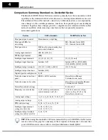
Comparison Summary, Standard vs. DeviceNet Series
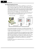
The Hitachi L100DN DeviceNet Series inverters generally have the same motor control
capability as the standard L100 inverters. However, a few important differences do exist.
The addition of DeviceNet network connectivity to Hitachi inverters is accompanied by
some changes to the available parameters, functions, front panel keypad, and intelligent
terminals. Together, these changes provide a complete inverter solution with DeviceNet
network capability, while removing some features that are generally unused in
networked applications.
TIP:
When using the standard L100 Series manual with your L100DN DeviceNet series
inverter, refer to this page for a summary of the exceptions to that manual. Also note that
your L100DN inverter comes with its own Quick Reference Guide (QRG).
Feature
L100 (standard)
L100DN (DeviceNet)
Front panel speed control
Potentiometer, output freq.
—
Front panel LEDs for
networking
—
MS – Module Status LED,
NS – Network Status LED
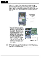
Front panel door
Half door for programming keys
and control terminals
—
Analog input terminals
[H], [O], [OI], [L]
—
PWM output terminal
[FM]
—
Intelligent input terminals
[1], [2], [3], [4], [5]
[1], [2], [3] only
Intelligent input functions
Includes [AT]
Includes [STA], [STP], [F/R],
[UP], [DWN], [DNT], [OPE]
Intelligent output terminals
[11], [12], [AL0] to [AL2]
[11], [12] only
Intelligent output functions
Includes [OD]
—
Digital operator configuration
B_89
—
Network connector on front
panel
RS422 or RJ11 modular
DeviceNet on Phoenix
5-terminal conn., male
Network connector for cable
—
DeviceNet on removable Phoenix
5-terminal conn., female
DeviceNet network settings
—
P_41to P_49
Frequency source selection
A_01 (selects potentiometer,
control terminal, or F_01)
A_01 does not exist, so freq.
source is always F_01 or the
DeviceNet network host
Analog input settings
A_11 to A_16, B_81, C_81, C_82
—
Analog output settings
C_23
—
PID control settings
D_04, A_71 to A_76, C_44
—
Intelligent input terminal
settings for [4] to [6]
C_04, C_05, C_06,
C_14, C_15, C_16
—
Intelligent output terminal
settings for [AL0] to [AL2]
C_24, C_33
—
Summary of Contents for L100DN DeviceNet Series Addendum
Page 96: ......


