Using Intelligent Input Terminals
Oper
ations
and Monitor
ing
4–32
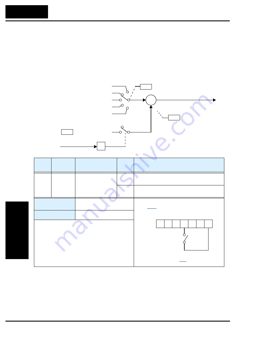
ADD Frequency Enable
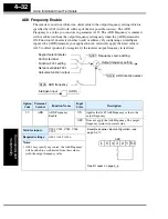
The inverter can add or subtract an offset value to the output frequency setting which is
specified by A001 (will work with any of the five possible sources). The ADD
Frequency is a value you can store in parameter A145. The ADD Frequency is summed
with or subtracted from the output frequency setting only when the [ADD] terminal is
ON. Function A146 selects whether to add or subtract. By configuring an intelligent
input as the [ADD] terminal, your application can selectively apply the fixed value in
A145 to offset (positively or negatively) the inverter output frequency in real time.
A001
Function F001 setting
Control terminal
Network variable F001
Calculate function output
Keypad potentiometer
A145
+
∑
+/–
ADD frequency
Frequency source setting
Output frequency setting
[ADD]
Intelligent input
A146 ADD direction select
Option
Code
Terminal
Symbol
Function Name
Input
State
Description
50
ADD
ADD Frequency
Enable
ON
Applies the A145 Add Frequency value to the
output frequency.
OFF
Does not apply the Add Frequency. The output
frequency retains its normal value.
Valid for inputs:
C001, C002, C003, C004,
C005
Required settings:
A001, A145, A146
Notes:
•
A001 may specify any source; the Add Frequency
will be added to or subtracted from that value to
yield the output frequency value.
Example (requires input configuration—see
page
See I/O specs on page
ADD
1
2
3
4
5
L
PCS
Summary of Contents for L200-002NFE2
Page 2: ......
Page 46: ......
Page 80: ......
Page 204: ......
Page 212: ......
Page 229: ...Glossary and Bibliography In This Appendix page Glossary 2 Bibliography 8 A ...
Page 280: ......
Page 297: ...L2002 Inverter Appendix D D 5 L1 L2 L3 PE L2002 inverter with book type filter M 3 ...

