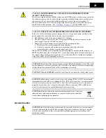
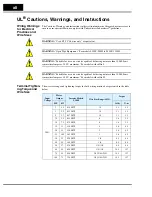
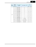
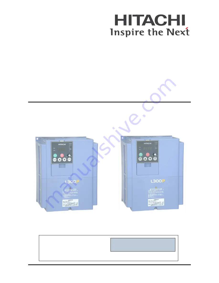
background image

L300P Series Inverter 
Instruction Manual

•Three-phase Input 200V Class
•Three-phase Input 400V Class

U.S. Version Models

European Version Models

After reading this manual,

keep it handy for future reference.

Hitachi Industrial Equipment Systems Co., Ltd.

Manual Number: NB604XJ

September 2006

Cover

Summary of Contents for L300P Series

Page 1: ...ee phase Input 200V Class Three phase Input 400V Class U S Version Models European Version Models After reading this manual keep it handy for future reference Hitachi Industrial Equipment Systems Co Ltd Manual Number NB604XJ September 2006 Cover ...

Page 2: ......

Page 3: ...d lead to serious results Important safety measures are described in CAUTION as well as WARNING so be sure to observe them STEP A step is one of a series of action steps required to accomplish a goal The number of the step will be contained in the step symbol NOTE Notes indicate an area or subject of special merit emphasizing either the product s capabilities or common errors in operation or maint...

Page 4: ...fore performing maintenance or an inspection Otherwise there is the danger of electric shock CAUTION These instructions should be read and clearly understood before working on L300P series equipment CAUTION Proper grounds disconnecting devices and other safety devices and their location are the responsibility of the user and are not provided by Hitachi Industrial Equipment Systems Co Ltd CAUTION B...

Page 5: ...nce with BS EN60204 1 Refer to the section Step by Step Basic Installation on page 2 6 The diagram dimensions are to be suitably amended for your application CAUTION Connection to field wiring terminals must be reliably fixed having two indepen dent means of mechanical support Using a termination with cable support figure below or strain relief cable clamp etc CAUTION A three pole disconnection de...

Page 6: ...operate an inverter that is damaged or has missing parts Otherwise it may cause injury to personnel 2 6 CAUTION Be sure to install the inverter in a well ventilated room that does not have direct exposure to sunlight a tendency for high temperature high humidity or dew condensation high levels of dust corrosive gas explosive gas inflammable gas grinding fluid mist salt air etc Otherwise there is t...

Page 7: ...e there is a danger of electric shock and or injury to personnel 2 13 Wiring Cautions for Electrical Practices CAUTION Be sure that the input voltage matches the inverter specifica tions Three phase 200 to 240V 50 60Hz Three phase 380 to 480V 50 60Hz 2 19 CAUTION Be sure not to power a three phase only inverter with single phase power Otherwise there is the possibility of damage to the inverter an...

Page 8: ...ze these components properly each must have the capacity for rated current and voltage Otherwise there is the danger of fire 2 19 CAUTION Failure to remove all vent opening covers before electrical operation may result in damage to the inverter 2 20 Powerup Test Caution Messages CAUTION The heat sink fins will have a high temperature Be careful not to touch them Otherwise there is the danger of ge...

Page 9: ... is enabled Be sure to enable the Stop Key separately from the emergency stop Otherwise it may cause injury to personnel 4 3 WARNING During a trip event if the alarm reset is applied and the Run command is present the inverter will automatically restart Be sure to apply the alarm reset only after verifying the Run command is OFF Otherwise it may cause injury to personnel 4 3 WARNING Be sure not to...

Page 10: ...utions for Troubleshooting and Maintenance WARNING Wait at least five 5 minutes after turning OFF the input power supply before performing maintenance or an inspection Otherwise there is the danger of electric shock 6 2 WARNING Make sure that only qualified personnel will perform mainte nance inspection and part replacement Before starting to work remove any metallic objects from your person wrist...

Page 11: ...ccurrence may harm humans then install an electromagnetic contactor on the power supply side so that the circuit does not allow automatic restarting after the power supply recov ers If an optional remote operator is used and the retry function has been selected this will also allow automatic restarting when a Run command is active So please be careful CAUTION Do not operate the inverter unless you...

Page 12: ...to noise interference they should be used well away from the inverter It is also effective to shield the whole inverter structure The addition of an EMI filter on the input side of the inverter also reduces the effect of noise from the commercial power line on external devices Note that the external dispersion of noise from the power line can be minimized by connecting an EMI filter on the primary...

Page 13: ...e you MUST install an input side AC reactor of 3 at a voltage drop at rated current with respect to the supply voltage on the power supply side Also where the effects of an indirect lightning strike are possible install a lightning conductor CAUTION Do not install inverters in a corner grounded Delta distribution system The result ing line imbalance will cause premature line fuse failure and failu...

Page 14: ... use on a circuit capable of delivering not more than 100 000 rms symmetrical amperes 480 V maximum For models with suffix H Terminal Tighten ing Torque and Wire Size The wire size range and tightening torque for field wiring terminals are presented in the table below Input Voltage Motor Output Inverter Models L300P Wire Size Range AWG Torque HP kW ft lbs N m 200V 2 1 5 015LFU2 14 1 1 1 5 3 2 2 02...

Page 15: ...0 7 5 075HFU2 HFE2 12 1 8 2 5 15 11 110HFU2 HFE2 8 3 6 4 9 20 15 150HFU2 HFE2 6 3 6 4 9 25 18 5 185HFU2 HFE2 6 3 6 4 9 30 22 220HFU2 HFE2 4 3 6 4 9 40 30 300HFU2 HFE2 3 3 6 4 9 50 37 370HFU2 HFE2 1 3 6 4 9 60 45 450HFU2 HFE2 1 6 5 8 8 75 55 550HFU2 HFE2 1 0 AWG 6 5 8 8 100 75 750HFU2 HFE2 1 0 1 0 AWG 6 5 8 8 125 90 900HFU2 HFE2 3 0 1 0 1 0 AWG 10 1 13 7 150 110 1100HFU2 HFE2 2 0 2 0 AWG 10 1 13 7 ...

Page 16: ...s are connected to the inverter they cannot be protected by the electronic overload protection Install an external thermal relay on each motor Input Voltage Motor Output 200V Inverter Models L300P AmpereRating for Fuse or Breaker Input Voltage Motor Output 400V Inverter Models L300P AmpereRating for Fuse or Breaker HP kW HP kW 200V 2 1 5 015LFU2 10 400V 2 1 5 015HFU2 HFE2 10 3 2 2 022LFU2 15 3 2 2...

Page 17: ...eypad 2 23 Chapter 3 Configuring Drive Parameters Choosing a Programming Device 3 2 Using Keypad Devices 3 3 D Group Monitoring Functions 3 6 F Group Main Profile Parameters 3 8 A Group Standard Functions 3 9 B Group Fine Tuning Functions 3 28 C Group Intelligent Terminal Functions 3 43 H Group Motor Constants Functions 3 56 P Group Expansion Card Functions 3 57 U Group User selectable Menu Functi...

Page 18: ...6 9 Maintenance and Inspection 6 10 Warranty 6 18 Appendix A Glossary and Bibliography Glossary A 2 Bibliography A 6 Appendix B Serial Communications Introduction B 2 Communications Protocol B 5 Communications Reference Information B 17 Appendix C Drive Parameter Settings Tables Introduction C 2 Parameter Settings for Keypad Entry C 2 Appendix D CE EMC Installation Guidelines CE EMC Installation G...

Page 19: ...MD descriptions to Chapter 3 tables Chapter 4 terminal listing and terminal description pages For new xFU2 models added new function P050 to Chapter 3 descriptions and Appendix C parameter listing Changed xFU models references to xFU2 throughout Added index entries for new xFU2 functions Expanded derating curve graphs in Chapter 1 Corrected FM common terminal to L in Chapter 4 Analog Input section...

Page 20: ... NY 10591 U S A Phone 1 914 631 0600 Fax 1 914 631 3672 Hitachi Australia Ltd Level 3 82 Waterloo Road North Ryde N S W 2113 Australia Phone 61 2 9888 4100 Fax 61 2 9888 4188 Hitachi Europe GmbH Am Seestern 18 D 40547 Düsseldorf Germany Phone 49 211 5283 0 Fax 49 211 5283 649 Hitachi Industrial Equipment Systems Co Ltd AKS Building 3 Kanda Neribei cho Chiyoda ku Tokyo 101 0022 Japan Phone 81 3 434...

Page 21: ...Getting Started In This Chapter page Introduction 2 L300P Inverter Specifications 6 Introduction to Variable Frequency Drives 16 Frequently Asked Questions 20 1 ...

Page 22: ...allow configuration from a PC and for field bus external modules Sixteen programmable speed levels PID control adjusts motor speed automatically to maintain a process variable value The design of Hitachi inverters overcomes many of the traditional trade offs between speed torque and efficiency The performance characteristics are Continuous operation at 100 rated torque within a 1 10 speed range 6 ...

Page 23: ...d unit to the connector in the inverter keypad recess See Chapter 3 for information on how to install and use these keypads and cables The digital operator copy unit is optional and occupies the entire keypad recess when mounted It has the additional capability of reading uploading the parameter settings in the inverter into its memory Then you can install the copy unit on another inverter and wri...

Page 24: ...or parts replacement Details on how and when to remove these parts are in the referenced chapters Fan Unit See Chapter 6 for servicing Control Signal Terminal Block See Chapter 4 for wiring Cable entry exit plate See Chapter 2 for instructions Capacitor Bank for DC Link See Chapter 6 for servicing Digital Operator and Panel Filler Plate See Chapter 3 for instructions Auxiliary fan on some models ...

Page 25: ... number legend below Product Labels Power Input Rating frequency voltage phase current Inverter model number Motor capacity for this model Output Rating frequency voltage current Manufacturing codes lot number date etc Specifications Regulatory agency approvals L300P 110 H F U 2 Version number _ 2 3 Restricted distribution E Europe U U S R Japan Input voltage H three phase 400V class L three phase...

Page 26: ...at 100 output 125 160 235 325 425 Dynamic braking approx torque short time stop 7 without ext res 50 20 with external res 200 160 100 80 DC braking Variable operating frequency time and braking force Weight kg lb 3 5 7 7 3 5 7 7 3 5 7 7 3 5 7 7 5 11 Item 200V Class Specifications L300P 200V models U S version 110LFU2 150LFU2 185LFU2 220LFU2 300LFU2 Applicable motor size 4 pole 2 HP 15 20 25 30 40 ...

Page 27: ...rox torque short time stop 7 without external braking unit 10 10 10 10 with external res and braking unit 45 90 35 75 30 60 30 60 DC braking Variable operating frequency time and braking force Weight kg lb 20 44 30 66 30 66 50 110 Item 400V Class Specifications L300P inverters 400V models U S version 015HFU2 022HFU2 040HFU2 055HFU2 075HFU2 European ver 015HFE2 022HFE2 040HFE2 055HFE2 075HFE2 Appli...

Page 28: ...C braking Variable operating frequency time and braking force Weight kg lb 5 11 5 11 12 26 4 12 26 4 12 26 4 20 44 Item 400V Class Specifications L300P inverters 400V models U S version 450HFU2 550HFU2 750HFU2 900HFU2 1100HFU2 1320HFU2 European ver 450HFE2 550HFE2 750HFE2 900HFE2 1100HFE2 1320HFE2 Applicable motor size 2 HP 60 75 100 125 150 175 kW 45 55 75 90 110 132 Rated capacity 400 480V kVA 5...

Page 29: ... source SFT software lock AT analog input voltage current select RS reset inverter STA start 3 wire interface STP stop 3 wire interface F R FW RV 3 wire interface PID PID ON OFF PIDC PID reset CAS control gain setting UP remote control Up function motorized speed pot DWN remote control Down function motorized speed pot UDC remote control data clearing OPE Operator control SF1 SF7 Multispeed bits 0...

Page 30: ... cables factory I O network interface cards Operator input devices 9 OPE SRE 4 digit LED with potentiometer OPE S 4 digit LED w o potentiometer Optional OPE SR 4 digit LED with potentiometer Japanese English overlay SRW 0EX Multilingual operator with copy function English French German Italian Spanish and Portuguese Item General Specifications Signal Contact Ratings Built in power for inputs 24VDC...

Page 31: ...rative torque use the optional regenerative braking unit and resistor see Chapter 5 Note 6 The storage temperature refers to the short term temperature during transport Note 7 Conforms to the test method specified in JIS C0911 1984 For the model types excluded in the standard specifications contact your Hitachi sales representative Note 8 When using the inverter in a dust prone area we recommend t...

Page 32: ...y Ambient tempera ture is the temperature just outside the inverter housing such as inside the control cabinet where the inverter is mounted A higher ambient temperature decreases derates the inverter s maximum current output capacity Use the following derating curves to help determine the optimal carrier frequency setting for your inverter and to find the output current derating Be sure to use th...

Page 33: ...0V class 2 4 6 8 10 12 0 5 65 70 75 80 85 90 95 100 Carrier Frequency kHz of Drive s Rated Amps 60 55 370L 300L 370L 300L L300P 45 to 75 kW 200V class 2 4 6 8 10 12 0 5 65 70 75 80 85 90 95 100 Carrier Frequency kHz of Drive s Rated Amps 450L 60 55 550L 750L 550L 450L 750L 750L 550L ...

Page 34: ...0 5 65 70 75 80 85 90 95 Carrier Frequency kHz of Drive s Rated Amps 60 55 300H 370H L300P 30 to 37 kW 400V class 015H 022H 030H 040H 055H 075H 110H 150H 185H 220H 2 4 6 8 10 12 0 5 65 70 75 80 85 90 95 Carrier Frequency kHz of Drive s Rated Amps 60 55 185H 220H 110H 150H L300P 1 5 to 22 kW 400V class ...

Page 35: ...5 70 75 80 85 90 95 100 Carrier Frequency kHz of Drive s Rated Amps 1100H 1320H 60 55 900H L300P 90 to 132 kW 400V class 2 4 6 8 10 12 0 5 65 70 75 80 85 90 95 Carrier Frequency kHz of Drive s Rated Amps 60 55 750H 450H 750H 450H 550H 900H 1100H 1320H 550H L300P 45 to 75 kW 400V class ...

Page 36: ...ng of the inverter shows three double throw switches In Hitachi inverters the switches are actually IGBTs isolated gate bipolar transistors Using a commutation algorithm the microprocessor in the drive switches the IGBTs ON and OFF at a very high speed to create the desired output waveforms The inductance of the motor windings helps smooth out the pulses Torque and Constant Volts Hertz Operation I...

Page 37: ...nverter s output terminals The output terminals are uniquely labeled to differentiate them from the input terminals with the designations U T1 V T2 and W T3 This corresponds to typical motor lead connection designa tions T1 T2 and T3 It is often not necessary to connect a particular inverter output to a particular motor lead for a new application The consequence of swapping any two of the three co...

Page 38: ...celeration but may also occur even when the load attempts to drive the motor faster than the desired speed overhauling If you need the motor and load to decelerate quicker than their natural deceleration during coasting we recommend installing a braking resistor The dynamic braking unit built into certain L300P models sends excess motor energy into a resistor to slow the motor and load see Introdu...

Page 39: ...more preset speeds which you can select via intelligent input terminals This external control can apply any preset speed at any time Alternatively the selected speed is infinitely variable across the speed range You can use the potentiometer control on the keypad for manual control The drive accepts analog 0 10V signals and 4 20 mA control signals as well The inverter can drive the motor in either...

Page 40: ...r interface or the PC software DOP Professional provide features beyond what is available from the keypad on the unit A Yes However note first that the same set of parameters and functions are equally accessible from either the unit s keypad or from remote devices The DOP Profes sional PC software lets you save or load inverter configurations to or from a disk file And the hand held digital operat...

Page 41: ...such as friction to serve as the decelerating force or otherwise can tolerate a long decel time These applications will not need dynamic braking However applications with a combina tion of a high inertia load and a required short decel time will need dynamic braking This is a physics question that may be answered either empirically or through exten sive calculations Q Several options related to el...

Page 42: ......

Page 43: ...Inverter Mounting and Installation In This Chapter page Orientation to Inverter Features 2 Basic System Description 5 Step by Step Basic Installation 6 Powerup Test 21 Using the Front Panel Keypad 23 2 ...

Page 44: ...r just after operation it can be very hot The electronics housing and front panel are built onto the front of the heat sink The front panel has three levels of physical access designed for convenience and safety First level access for basic use of inverter and editing parameters during powered opera tion power is ON Second level access for wiring the inverter power supply or motor power is OFF Thi...

Page 45: ... rubber grommets below the power terminals are for wire entry exit to the power source and motor Never operate the inverter with the front panel removed The control terminals connect logic or analog signals for control and monitoring of the inverter The nearby alarm relay provides both normally open and normally closed logic for interface to an external alarm The alarm circuit may carry hazardous ...

Page 46: ...t the bottom then disengage the two hinge latches at the top The expansion bay has two sites for adding expansion cards Each card connects via the interface connector and mounts using three standoff screw locations Further details on accessories are in Chapter 5 You may also refer to the instruction manual that comes with each type of expansion card The following sections will describe the system ...

Page 47: ...terference may occur on nearby equipment such as a radio receiver This magnetic choke filter helps reduce radiated noise can also be used on output EMI filter for CE applications see Appendix D This filter reduces the conducted noise in the power supply wiring between the inverter and the power distribution system Connect it to the inverter primary input side Radio noise filter use in non CE appli...

Page 48: ...CAUTION Be sure to install the unit on flame resistant material such as a steel plate Other wise there is the danger of fire CAUTION Be sure not to place any flammable materials near the inverter Otherwise there is the danger of fire CAUTION Be sure not to let the foreign matter enter vent openings in the inverter housing such as wire clippings spatter from welding metal shavings dust etc Otherwis...

Page 49: ...This will prevent harmful debris such as wire clippings and metal shavings from entering the inverter during installation Please observe this checklist while mounting the inverter 1 The ambient temperature must be in the range of 10 to 40 C If the range will be up to 50 C maximum rating you will need to refer to Derating Curves on page 1 12 2 Keep any other heat producing equipment as far away fro...

Page 50: ...5HFU2 022LFU2 022HFU2 037LFU2 037HFU2 055LFU2 055HFU2 150 5 91 130 5 12 2 φ 6 0 24 241 9 49 255 10 04 295 11 61 130 5 12 108 4 25 3 φ 28 1 10 Wiring hole knockout Exhaust Air intake Conduit box 40 1 57 6 0 24 10 0 39 21 0 83 64 5 2 54 75 2 95 140 5 51 62 2 44 7 0 28 143 5 63 10 0 39 7 0 28 40 1 57 108 4 25 Model L300P 075LFU2 075HFU2 HFE2 110LFU2 110HFU2 HFE2 150LFU2 150HFU2 HFE2 Wiring hole knock...

Page 51: ... 0 28 10 5 0 41 250 9 84 229 9 02 390 15 35 376 14 80 10 5 0 41 229 9 02 204 8 03 3 φ 44 1 73 Exhaust Air intake 537 21 14 86 3 39 104 4 09 244 9 61 190 7 48 9 5 0 37 83 3 27 147 5 79 147 5 79 104 4 09 Model L300P 370LFU2 370HFU2 HFE2 310 12 20 265 10 43 2 φ 10 0 39 510 20 08 540 21 26 510 20 08 685 26 97 2 10 0 39 265 10 43 307 12 09 74 2 91 15 0 59 22 5 0 89 22 5 0 89 175 6 89 1 5 0 06 195 7 68 ...

Page 52: ...5 35 300 11 81 45 1 77 520 20 47 705 27 76 520 20 47 550 21 65 185 7 28 185 7 28 250 9 84 90 3 54 154 6 06 387 15 23 1 5 0 06 300 11 81 45 1 77 2 φ 12 0 47 2 12 0 47 Model L300P 750LFU2 700 27 56 670 26 38 480 18 90 380 14 96 50 1 97 860 33 86 670 26 38 190 7 48 380 14 96 250 9 84 Exhaust Air intake Optional adapter for NEMA1 rating 2 12 0 47 50 1 97 480 18 90 476 18 74 2 0 08 190 7 48 104 4 09 10...

Page 53: ... and Installation 2 11 Dimensional drawings continued Model L300P 900HFU2 HFE2 1100HFU2 HFE2 700 27 56 670 26 38 300 11 81 390 15 34 270 10 63 2 φ 12 0 47 2 12 0 47 Air intake Exhaust Optional adapter for NEMA1 rating 90 3 54 185 7 28 ...

Page 54: ...erter Mounting and Installation 2 12 Dimensional drawings continued Model L300P 1320HFU2 HFE2 740 29 13 710 27 95 380 14 96 2 φ 12 0 47 2 12 0 47 480 18 90 270 10 63 Air intake Exhaust Optional adapter for NEMA1 rating 190 7 48 104 4 09 ...

Page 55: ...Equipment WARNING A Class 2 circuit wired with Class 1 wire or equivalent WARNING Suitable for use on a circuit capable of delivering not more than 100 000 rms symmetrical amperes 240 V maximum For models with suffix L WARNING Suitable for use on a circuit capable of delivering not more than 100 000 rms symmetrical amperes 480 V maximum For models with suffix H HIGH VOLTAGE Be sure to ground the u...

Page 56: ...only applies to a few models that have a built in braking unit The other models use an optional external braking unit Parallel wires increase effective wire gauge and are denoted by in the tables Signal Lines not listed in these tables connect to the removable logic connector The recom mended wire gauge for all wiring to the logic connector is 28 AWG 0 75 mm2 Be sure to use shielded wire for any a...

Page 57: ... type 2 AWG rec AWG UL mm2 AWG mm2 2 1 5 015HFU2 HFE2 20 2 10A 10A 16 14 1 25 18 2 3 2 2 022HFU2 HFE2 18 2 10A 10A 16 14 1 25 16 2 5 4 0 040HFU2 HFE2 16 2 15A 15A 16 14 1 25 14 2 7 5 5 5 055HFU2 HFE2 14 2 15A 30A 14 14 2 12 2 10 7 5 075HFU2 HFE2 12 3 5 20A 30A 10 12 3 5 10 3 5 15 11 110HFU2 HFE2 8 5 5 30A 50A 8 10 5 5 8 5 5 20 15 150HFU2 HFE2 6 8 35A 60A 8 10 8 8 5 5 25 18 5 185HFU2 HFE2 6 14 50A ...

Page 58: ...re 6 6M 8 8M 10 10M TIP AWG American Wire Gauge Smaller numbers represent increasing wire thickness kcmil 1 000 circular mils a measure of wire cross sectional area mm2 square millimeters a measure of wire cross sectional area Input Voltage Motor Output 200V Inverter Models L300P Screw size of terminal Ring Lug Connector 1 Torque HP kW AWG bolt mm2 bolt ft lbs N m 200V 2 1 5 015LFU2 M4 14 10 2 4 1...

Page 59: ... ft lbs N m 400V 2 1 5 015HFU2 HFE2 M4 20 10 2 4 1 1 1 5 3 2 2 022HFU2 HFE2 M4 18 10 2 4 1 1 1 5 5 4 0 040HFU2 HFE2 M4 16 10 2 4 1 1 1 5 7 5 5 5 055HFU2 HFE2 M5 14 12 2 5 1 8 2 5 10 7 5 075HFU2 HFE2 M5 12 12 3 5 5 1 8 2 5 15 11 110HFU2 HFE2 M6 8 1 4 5 5 6 3 6 4 9 20 15 150HFU2 HFE2 M6 6 1 4 8 6 3 6 4 9 25 18 5 185HFU2 HFE2 M6 6 1 4 14 6 3 6 4 9 30 22 220HFU2 HFE2 M6 4 1 4 14 6 3 6 4 9 40 30 300HFU...

Page 60: ...00P 110LFU2 inverter The terminal locations will vary depending on the inverter model see below Note the use of ring lug connectors for a secure connection Please use the terminal arrangement below corresponding to your inverter model 6 Wire the Inverter Input to a Supply R L1 V T2 U T1 W T3 S L2 T L3 PD 1 RB RB P N G G R0 R0 T0 T0 R L1 V T2 U T1 W T3 S L2 T L3 PD 1 P N R0 R0 T0 T0 075LFU2 075HFU2...

Page 61: ...er leakage current toward Earth GND Especially at the moment of switching ON this can cause an inadvertent trip of ground fault interrupter breakers Because of the recti fier on the input side of the inverter there is the possibility to stall the switch off function through small amounts of DC current Please observe the following Use only short time invariant and pulse current sensitive ground fau...

Page 62: ...as you used on the power input wiring in the previous step After completing the wiring Check the mechanical integrity of each wire crimp and terminal connection Replace the front panel and secure the retention screw firmly Logic Control Wiring After completing the initial installation and powerup test in this chapter you may need to wire the logic signal connector for your application For new inve...

Page 63: ... a brief introduction to the use of the built in operator keypad The powerup test gives you an important starting point to ensure a safe and successful applica tion of the Hitachi inverter We highly recommend performing this test before proceeding to the other chapters in this manual Pre test and Operational Precautions The following instructions apply to the powerup test or to any time the invert...

Page 64: ...e inverter trip during acceleration or deceleration Were the rpm and frequency meter readings as expected Were there any abnormal motor vibrations or noise Powering the Inverter If you have followed all the steps cautions and warnings up to this point you re ready to apply power After doing so the following events should occur The POWER LED will illuminate The numeric 7 segment LEDs will display a...

Page 65: ...s this key to run the motor the Run Enable LED must be ON first Parame ter F004 Keypad Run Key Routing determines whether the Run key generates a Run FWD or Run REV command Stop Reset Key Press this key to stop the motor when it is running uses the programmed deceleration rate This key will also reset an alarm that has tripped Potentiometer allows an operator to directly set the motor speed when t...

Page 66: ...Hz To edit the parameter the inverter must be in Program Mode PGM LED will be ON You use the front panel keys to first select the function code A004 After displaying the value for A004 use the Up Down or keys to edit the value NOTE The inverter 7 segment display shows lower case b and d meaning the same as the upper case letters B and D used in this manual for uniformity A to F The inverter automa...

Page 67: ...rs and functions in the diagram below You can later use this map as a reference 1 2 2 1 Write data to EEPROM store as powerup default Increment decrement value 2 1 2 1 2 1 2 1 2 1 2 1 2 1 1 Select Parameter Select Function Display Data 2 Return to parameter list 2 1 2 1 2 1 2 1 2 1 2 1 Edit Parameter 2 1 2 1 2 1 2 1 2 1 2 1 d 09 0 U P H C b A U01 2 U001 P05 0 P001 H2 06 H003 C 1 2 3 C 001 b 1 1 3 ...

Page 68: ...ications with the respective manufacturer Only operate the motor at elevated frequencies after getting their approval Otherwise there is the danger of equipment damage Setting the Motor Base Frequency The motor is designed to operate at a specific AC frequency Most commercial motors are designed for 50 60 Hz operation First check the motor specifications Then follow the steps in the table below to...

Page 69: ... the RUN Command the table resumes action from the end of the previous table NOTE When you press the STR key in the last step above and the display 02 the Run Enable LED above the RUN switch on the keypad will turn ON This is normal and does not mean the motor is trying to run It means that the RUN key is now enabled DO NOT press the RUN key at this time finish out the programming exercise first A...

Page 70: ... you became lost during any of these steps first observe the state of the PRG LED Then study the Keypad Navigational Map on page 2 25 to determine the current state of the keypad controls and display As long as you do not press the STR key no parameters will be changed by keypad entry errors Note that power cycling the inverter will not cause it to reset to a particular programming state The next ...

Page 71: ...you are selecting the particular monitoring param eter After pressing the FUNC key the display shows the current speed is zero at this point Running the Motor If you have programmed all the parameters up to this point you re ready to run the motor First review this checklist 1 Verify the Power LED is ON If not check the power connections 2 Verify the Run Key Enable LED is ON If not review the prog...

Page 72: ...er an induction motor cannot generate torque unless its shaft turns at a slightly different speed This difference is called slip So it s common to see a rated speed of approximately 1750 RPM on a 60 Hz 4 pole motor Using a tachometer to measure shaft speed you can see the difference between the inverter output frequency and the actual motor speed The slip increases slightly as the motor s load inc...

Page 73: ...roup Monitoring Functions 6 F Group Main Profile Parameters 8 A Group Standard Functions 9 B Group Fine Tuning Functions 28 C Group Intelligent Terminal Functions 43 H Group Motor Constants Functions 56 P Group Expansion Card Functions 57 U Group User selectable Menu Functions 59 Programming Error Codes 60 3 ...

Page 74: ...ific individual changes and observing their effects you can achieve a finely tuned system Inverter Programming Keypads The front panel keypad is the first and best way to get to know the inverter s capabilities Every function or programmable parameter is accessible from the keypad All keypads have the same basic layout but with different features The OPE SRE has a potentiometer knob for frequency ...

Page 75: ... speed when the potentiometer is enabled for output frequency control Potentiometer Enable LED ON when the potentiometer is enabled for value entry Parameter Display a 4 digit 7 segment display for parameters and function codes Display Units Hertz Volts Amperes kW These LEDs indicate the units associated with the parameter display When the display is monitoring a parameter the appropriate LED is O...

Page 76: ...1 Write data to EEPROM store as powerup default Increment decrement value 2 1 2 1 2 1 2 1 2 1 2 1 2 1 1 Select Parameter Select Function Display Data 2 Return to parameter list 2 1 2 1 2 1 2 1 2 1 2 1 Edit Parameter 2 1 2 1 2 1 2 1 2 1 2 1 d 09 0 U P H C b A U01 2 U001 P05 0 P001 H2 06 H003 C 1 2 3 C 001 b 1 1 3 b 001 A1 3 2 A001 1 2 3 4 0 00 d 001 F 004 F 001 2 1 P04 9 d 001 D002 D090 Edit 0 00 D...

Page 77: ...he parameter can be edited You ll notice in the table example to the right the two adjacent marks The two marks that can also be or correspond to these levels of access to editing Low access level to Run Mode edits indicated by left most mark High access level to Run Mode edits indicated by right most mark The Software Lock Setting parameter B031 determines the particular access level that is in e...

Page 78: ...tput current to motor 100 mS internal filter time constant A Iout 0000 0A D003 Rotation direction monitor Three different indications F Forward o Stop r Reverse Dir STOP D004 Process variable PV PID feedback monitor Displays the scaled PID process variable feedback value A75 is scale factor PID FB 0000 00 D005 Intelligent input terminal status Displays the state of the intelligent input terminals ...

Page 79: ...ter has been in RUN mode in hours Range is 0 to 9999 1000 to 9999 100 to 999 10 000 to 99 900 hrs hours RUN 0000000hr D017 Cumulative power on time monitor Displays total time the inverter has had input power ON in hours Range is 0 to 9999 100 0 to 999 9 1000 to 9999 100 to 999 hrs hours ON 0000000hr D Function Run Mode Edit Range and Units SRW Display Func Code Name Description D Function Run Mod...

Page 80: ...2nd in use at a particular time Output frequency F001 F002 F003 t F Function Run Mode Edit Lo Hi Defaults Units SRW Display Func Code Name Description FE2 EU FU2 US FR JP F001 Output frequency setting Standard default target frequency that determines constant motor speed Range is 0 to 400 Hz 0 00 0 00 0 00 Hz F001 SET Freq TM 0000 00Hz 2FS 0000 00Hz 3FS 0000 00Hz TM 0000 00Hz JG 0000 00Hz 1S 0000 ...

Page 81: ...ting range limited to the motor nameplate voltage and frequency rating then set the base frequency and maximum frequency equal as shown below right NOTE The 2nd motor settings in the tables in this chapter store an alternate set of parame ters for additional motors The inverter can use the 1st or 2nd set of parameters to generate the output frequency to the motor See Configuring the Inverter for M...

Page 82: ...2nd motor Settable from 30 Hz to the maximum frequency 50 60 60 Hz A203 2F BASE F 0060Hz A004 Maximum frequency setting Settable from 30 Hz to 400 Hz 50 60 60 Hz A004 F max F 0060Hz A204 Maximum frequency setting 2nd motor Settable from 30 Hz to 400 Hz 50 60 60 Hz A204 2F max F 0060Hz A Function Run Mode Edit Lo Hi Defaults Units SRW Display Func Code Name Description FE2 EU FU2 US FR JP ...

Page 83: ...the graph to the right A103 and A104 select the active portion of the input current range Parameters A101 and A102 select the start and end frequency of the converted output frequency range respec tively Together these four parameters define the major line segment as shown When the line does not begin at the origin A101 and A103 0 then A105 defines whether the inverter outputs 0Hz or the A101 spec...

Page 84: ... voltage input range starting point Range is 0 00 to 400 00 Hz 0 00 0 00 0 00 Hz A011 INPUT O EXS 0000 00Hz A012 O L input active range end frequency The output frequency corre sponding to the voltage input range ending point Range is 0 00 to 400 00 Hz 0 00 60 0 0 00 Hz A012 INPUT O EXE 0000 00Hz A013 O L input active range start voltage The starting point for the voltage input range Range is 0 to...

Page 85: ...ion selection Two options select codes 00 Binary up to 16 stage speed using 4 intelligent terminals 01 Single bit up to 8 stage speed using 7 intelligent terminals 00 00 00 A019 SPEED SELECT BINARY A020 Multi speed frequency setting Defines the first speed of a multi speed profile range is 0 to 360 Hz A020 Speed 0 1st motor 0 00 0 00 0 00 Hz A020 SPEED FS 0000 00Hz A220 Multi speed frequency setti...

Page 86: ...base frequency A003 The voltage remains constant for output frequencies higher than the base frequency The graph above right shows the general characteristic for variable torque The curve may be best described in three sections as follows a The range from 0Hz to 10 of the base frequency is the constant torque characteristic For example a base frequency of 60Hz ends the constant torque characterist...

Page 87: ... applies only to constant torque A044 00 and variable torque A044 01 V f control V f Free setting The free setting V f inverter mode of operation uses voltage and frequency parameter pairs to define seven points on a V f graph This provides a way to define a multi segment V f curve that best suits your application The frequency settings do require that F1 F2 F3 F4 F5 F6 F7 their values must have t...

Page 88: ...e boost 01 Automatic torque boost 00 00 00 A241 2V Boost Mode MANUAL A042 Manual torque boost value Can boost starting torque between 0 and 20 above normal V f curve from 0 to 1 2 base frequency 1 0 1 0 1 0 A042 V Boost Code 01 0 A242 Manual torque boost value 2nd motor Can boost starting torque between 0 and 20 above normal V f curve from 0 to 1 2 base frequency 1 0 1 0 1 0 A242 2V Boost Code 01 ...

Page 89: ...ng cases You can configure DC braking to initiate in one of two ways 1 Internal DC braking Set A051 01 to enable internal braking The inverter automatically applies DC braking as configured during stopping starting or both 2 External DC braking Configure an input terminal with option code 7 DB see Exter nal Signal for DC Injection Braking on page 4 16 for more details Leave A051 00 although this s...

Page 90: ...onds 0 0 0 0 0 0 sec A053 DCB WAIT 0 0s A054 DC braking force during deceleration Variable DC braking force Range is from 0 to 70 0 0 0 A054 DCB STP V 000 A055 DC braking time for deceleration Sets the duration for DC braking during decel Range is 0 0 to 60 0 seconds 0 0 0 0 0 0 sec A055 DCB STP T 00 0s A056 DC braking edge or level detection for DB input Two options select codes 00 Edge detection...

Page 91: ... Hi Defaults Units SRW Display Func Code Name Description FE2 EU FU2 US FR JP A061 Frequency upper limit setting Sets a limit on output frequency less than the maximum frequency A004 Range is 0 50 to 400 0 Hz 0 00 setting is disabled 0 10 setting is enabled 0 00 0 00 0 00 Hz A061 LIMIT HIGH 0000 00Hz A261 Frequency upper limit setting 2nd motor Sets a limit on output frequency less than the maximu...

Page 92: ...n ramp resumes See also DC Braking Settings on page 3 17 A Function Run Mode Edit Lo Hi Defaults Units SRW Display Func Code Name Description FE2 EU FU2 US FR JP A063 A065 A067 Jump center frequency setting Up to 3 output frequencies can be defined for the output to jump past to avoid motor resonances center frequency Range is 0 00 to 400 0 Hz 0 00 0 00 0 00 Hz A063 JUMP F1 0000 00Hz A065 JUMP F2 ...

Page 93: ...ion NOTE The setting A073 for the integrator is the integrator s time constant Ti not the gain The integrator gain Ki 1 Ti When you set A073 0 the integrator is disabled A Function Run Mode Edit Lo Hi Defaults Units SRW Display Func Code Name Description FE2 EU FU2 US FR JP A071 PID Enable Enables PID function two option codes 00 PID operation OFF 01 PID operation ON 00 00 00 A071 PID SW OFF A072 ...

Page 94: ...ion and A086 controls the degree of its effect A setting of 0 0 yields slow response but high accuracy while a setting of 100 will yield a fast response with lower accuracy A Function Run Mode Edit Lo Hi Defaults Units SRW Display Func Code Name Description FE2 EU FU2 US FR JP A081 AVR function select Automatic output voltage regulation selects from three type of AVR functions three option codes 0...

Page 95: ... 0 01 to 3600 sec 15 0 15 0 15 0 sec A092 ACCEL TIME2 0015 00s A292 Acceleration 2 time setting 2nd motor Duration of 2nd segment of acceleration 2nd motor range is 0 01 to 3600 sec 15 0 15 0 15 0 sec A292 2ACCEL TIME2 0015 00s A093 Deceleration 2 time setting Duration of 2nd segment of deceleration range is 0 01 to 3600 sec 15 0 15 0 15 0 sec A093 DECEL TIME2 0015 00s A293 Deceleration 2 time set...

Page 96: ...c1 or Dec1 in order to achieve the second ramp to the target frequency A096 Dec1 to Dec2 frequency transition point Output frequency at which Decel1 switches to Decel2 range is 0 00 to 400 0 Hz 0 0 0 0 0 0 Hz A096 DECEL CHFr 0000 00Hz A296 Dec1 to Dec2 frequency transition point 2nd motor Output frequency at which Decel1 switches to Decel2 range is 0 00 to 400 0 Hz 2nd motor 0 0 0 0 0 0 Hz A296 2D...

Page 97: ...time Output frequency time Output frequency time Output frequency Linear Sigmoid U shape Reverse U shape Accel A97 Decel A98 00 Set value Curve 01 02 03 Linear acceleration and deceleration for general purpose use Avoid jerk on start stop for elevators use for delicate loads on con veyors Tension control for winding applications web presses roller accumulators Typical applications A Function Run M...

Page 98: ... target time Output frequency 25 50 75 of target time Output frequency 25 50 75 of target 3 1 17 6 82 4 96 9 100 100 100 99 6 93 8 87 5 68 4 64 6 35 0 65 0 35 4 31 6 12 5 6 25 0 39 A Function Run Mode Edit Lo Hi Defaults Units SRW Display Func Code Name Description FE2 EU FU2 US FR JP A131 Acceleration curve constants setting Sets the curve deviation from straight line accelera tion in ten levels ...

Page 99: ... OI EXE 0000 00Hz A103 OI L input active range start current The starting point for the current input range Range is 0 to 100 20 20 20 A103 INPUT OI EX S 020 A104 OI L input active range end current The ending point for the current input range Range is 0 to 100 100 100 100 A104 INPUT OI EX E 100 A105 OI L input start frequency enable Two options 00 Use A101 start value 01 Use 0Hz 01 01 01 Hz A105 ...

Page 100: ... the inverter to reset its operation Other parameters specify the allowable under voltage level and the delay time before restarting The proper settings depend on the typical fault conditions for your application the necessity of restarting the process in unattended situations and whether restarting is always safe Input power Motor speed Power failure Inverter output Power failure allowable power ...

Page 101: ...de is selected If it exists less than this time retry will be attempted Range is 0 3 to 25 0 sec 1 0 1 0 1 0 sec b002 IPS TIME 1 0s B003 Retry wait time before motor restart Time delay after a trip condition goes away before the inverter restarts the motor Range is 0 3 to 100 seconds 1 0 1 0 1 0 sec b003 IPS WAIT 001 0s B004 Instantaneous power failure under voltage trip alarm enable Three option ...

Page 102: ...teristic adjusts the way the inverter calculates thermal heating based on the type of load connected to the motor as set by parameter B013 CAUTION When the motor runs at lower speeds the cooling effect of the motor s internal fan decreases The table below shows the torque profile settings Use the one that matches your load Reduced Torque Characteristic The left graph below shows the effect of the ...

Page 103: ...ow shows the region for possible free setting curves The right graph below shows an example curve defined by three data points specified by B015 B020 Function Code Name Description Range B015 B017 B019 Free setting electronic thermal frequency 1 2 3 Data point coordinates for Hz axis horizontal in the free form curve 0 to 400Hz B016 B018 B020 Free setting electronic thermal current 1 2 3 Data poin...

Page 104: ...inverter model A b012 E THM LEVEL 0016 5A B212 Level of electronic thermal setting 2nd motor Set a level between 50 and 120 of the inverter rated current rated current for each inverter model A b212 2E THM LEVEL 0016 5A B013 Electronic thermal characteristic Select from three curves option codes 00 Reduced torque 01 Constant torque 02 V f free setting 01 00 00 b013 E THM CHAR CRT B213 Electronic t...

Page 105: ... operation mode Select the operating mode during overload conditions three options option codes 00 Disabled 01 Enabled for acceleration and constant speed 02 Enabled for constant speed only 01 01 01 b021 OLOAD 1MODE ON B022 Overload restriction setting Sets the level for overload restriction between 50 and 150 of the rated current of the inverter setting resolution is 1 of rated current rated cur ...

Page 106: ...means of an intelligent input terminal see Overload Restriction on page 4 32 B026 Deceleration rate at overload restriction 2 Sets the deceleration rate 2 when inverter detects overload range is 0 1 to 30 0 resolution is 0 1 1 00 1 00 1 00 sec b026 OLOAD 2CONST 01 00 B Function Run Mode Edit Lo Hi Defaults Units SRW Display Func Code Name Description FE2 EU FU2 US FR JP ...

Page 107: ... speed operation selection The editing access to B031 itself is unique and is specified in the right most two columns below NOTE Since the software lock function B031 is always accessible when the motor is stopped this feature is not the same as password protection used in other industrial control devices NOTE To disable parameter editing when using B031 lock modes 00 and 01 assign the SFT functio...

Page 108: ...e inverter will not use the analog inputs nor their adjustment parameters for an external frequency command B Function Run Mode Edit Lo Hi Defaults Units SRW Display Func Code Name Description FE2 EU FU2 US FR JP B034 Run power on warning time Range is 0 to 65 530 hours 0 0 0 hrs b034 TIME WARN 00000 B035 Rotational direction restriction Three option codes 00 Enable for both dir 01 Enable for forw...

Page 109: ...tion A094 01 A095 A096 2 stage adjustable frequency A294 01 A0295 A296 B013 B213 02 B015 B020 Electric thermal characteris tic B021 01 02 B022 B023 Overload restriction B024 01 02 B025 B026 Overload restriction 2 B095 01 02 B090 B096 Dynamic braking function C001 C005 06 A038 A039 Jogging 08 A203 A204 A220 A241 A244 A261 A262 A292 A293 A296 B212 B213 H203 H204 H206 2nd motor control 11 B088 Free r...

Page 110: ...ttings Please refer to Restoring Factory Default Settings on page 6 9 B086 Frequency display scaling You can convert the output frequency monitor on D001 to a scaled number engineering units monitored at function D007 For example the motor may run a conveyor that is monitored in feet per minute Use this formula Scaled output frequency D007 Output frequency D001 Factor B086 B Function Run Mode Edit...

Page 111: ... INITIAL SELECT USA B086 Frequency scaling conversion factor Specify a constant to scale D007 to display in engineer ing units Range is 0 1 to 99 9 1 0 1 0 1 0 b086 F CONV Gain 001 0 B087 STOP key enable Select whether the STOP key on the keypad is enabled req A002 01 03 04 or 05 Two option codes 00 Enable 01 Disable 00 00 00 b087 STOP SW SELECT ON B Function Run Mode Edit Lo Hi Defaults Units SRW...

Page 112: ...n the inverter attempts to force the load quickly to zero speed NOTE Other events can cause or be configured to cause a free run stop such as power loss see Automatic Restart Mode and Phase Loss on page 3 28 and inverter trip events in general see Miscellaneous Functions on page 3 55 If all free run stop behavior is impor tant to your application such as HVAC be sure to configure each event accord...

Page 113: ...lects how the inverter normally stops the motor Run command or signal goes OFF Two option codes 00 DEC decelerate and stop 01 FRS free run to stop 00 00 00 b091 RUN STOP DEC B092 Cooling fan control see note below Two option codes 00 Fan always ON 01 Fan ON during RUN OFF during STOP 00 00 00 b092 INITIAL FAN CTL OFF B095 Dynamic braking control Three option codes 00 Disable 01 Enable during RUN o...

Page 114: ...Hz B102 Free setting V f frequency 2 V f point 2 frequency coordinate 0 0 0 Hz b103 FREE V F V2 000 0V B103 Free setting V f voltage 2 V F point 2 voltage coordi nate 0 0 0 0 0 0 V b104 FREE V F F2 0000Hz B104 Free setting V f frequency 3 V f point 3 frequency coordinate 0 0 0 Hz b105 FREE V F V3 000 0V B105 Free setting V f voltage 3 V F point 3 voltage coordi nate 0 0 0 0 0 0 V b106 FREE V F F3 ...

Page 115: ...any of the five logic inputs for the L300P inverters The functions C001 through C005 configure the terminals 1 through 5 respectively The value of these partic ular parameters is not a scalar value but it is a discrete number that selects one option from many available options For example if you set function C001 01 you have assigned option 01 Reverse Run to terminal 1 The option codes and the spe...

Page 116: ...d for normally closed operation C Function Run Mode Edit Lo Hi Defaults Units SRW Display Func Code Name Description FE2 EU FU2 US FR JP C011 Terminal 1 active state Select logic convention two option codes 00 normally open N O 01 normally closed N C 00 00 00 C011 IN TM O C 1 NO C012 Terminal 2 active state 00 00 00 C012 IN TM O C 2 NO C013 Terminal 3 active state 00 01 00 C013 IN TM O C 3 NO C014...

Page 117: ... speed select Bit 0 logical 1 OFF Binary encoded speed select Bit 0 logical 0 03 CF2 Multi speed select Bit 1 ON Binary encoded speed select Bit 1 logical 1 OFF Binary encoded speed select Bit 1 logical 0 04 CF3 Multi speed select Bit 2 ON Binary encoded speed select Bit 2 logical 1 OFF Binary encoded speed select Bit 2 logical 0 05 CF4 Multi speed select Bit 3 MSB ON Binary encoded speed select B...

Page 118: ...tion is reset the motor output is turned OFF and powerup reset is asserted OFF Normal power on operation 20 STA START 3 wire interface ON Starts the motor rotation OFF No change to present motor status 21 STP STOP 3 wire interface ON Stops the motor rotation OFF No change to present motor status 22 F R FWD REV 3 wire interface ON Selects the direction of motor rotation ON FWD While the motor is ro...

Page 119: ...N command A002 to be from the digital operator OFF Source of output frequency set by A001 and source of run command set by A002 is used 32 SF1 Multispeed bit 1 ON Logical 1 OFF Logical 0 33 SF2 Multispeed bit 2 ON Logical 1 OFF Logical 0 34 SF3 Multispeed bit 3 ON Logical 1 OFF Logical 0 35 SF4 Multispeed bit 4 ON Logical 1 OFF Logical 0 36 SF5 Multispeed bit 5 ON Logical 1 OFF Logical 0 37 SF6 Mu...

Page 120: ...c discrete outputs see next section 01 FA1 01 FA1 01 FA1 C021 OUT TM 11 FA1 C022 Terminal 12 function 00 RUN 00 RUN 00 RUN C022 OUT TM 12 RUN C026 Alarm relay terminal function 05 AL 05 AL 05 AL C026 OUT TM AL AL C027 FM signal selection 7 programmable functions available for analog outputs see after next section 00 output freq 00 output freq 00 output freq C027 FM MONITOR KIND A F C028 AM signal ...

Page 121: ...ut deviation for PID control ON when PID error is more than the set threshold for the deviation signal OFF when PID error is less than the set threshold for the deviation signal 05 AL Alarm signal ON when the alarm condition has been met and not reset OFF when the alarm had not tripped since the previous power cycle or since the previous keypad reset 06 FA3 Frequency arrival type 3 at frequency ON...

Page 122: ... command source monitor xFU2 and xFE2 models only ON when the Run command source is the operator keypad A002 02 OFF when the Run command source is not the operator keypad A002 01 03 04 or 05 Output Function Summary Table Option Code Terminal Symbol Function Name Description Analog Output Function Summary Table Option Code Function Name Description Corresponding Signal Range 00 Output frequency Act...

Page 123: ...the Setpoint desired value and Process Variable actual value The PID output deviation signal OD output terminal function option code 04 indicates when the error magnitude has exceeded a magnitude you define Motor current Overload signal C041 t 1 0 Output frequency Arrival signal C042 C043 t 1 0 PID Error PV SP Deviation Signal C044 t 1 0 SP C Function Run Mode Edit Lo Hi Defaults Units SRW Display...

Page 124: ...e value to trigger intelligent output OD Range is 0 0 to 100 resolution is 0 1 3 0 3 0 3 0 C044 PID LEVEL 003 0 C061 Electronic thermal warning level setting Sets the threshold for intelli gent output THM Range is 0 to 100 80 80 80 C061 E THM WARN 080 C Function Run Mode Edit Lo Hi Defaults Units SRW Display Func Code Name Description FE2 EU FU2 US FR JP ...

Page 125: ... option codes 02 Digital operator 03 RS485 04 Expansion Card 1 05 Expansion Card 2 02 02 02 C070 PARAM SELECT REM C071 Communication speed selection Five option codes 02 Test 03 2400bps 04 4800bps 05 9600bps 06 19200bps 04 04 04 bps C071 RS485 BAU 4800bps C072 Node allocation Set the address of the inverter on the network Range is 1 to 32 1 1 1 C072 RS485 ADDRESS 01 C073 Communication data length ...

Page 126: ...e Name Description FE2 EU FU2 US FR JP C081 O input span calibra tion Range is 0 to 65530 Factory calibrated C081 O ADJUST TOP 02119 C082 OI input span calibra tion Range is 0 to 65530 Factory calibrated C082 OI ADJUST TOP 02512 C083 O2 input span calibra tion Range is 0 to 65530 Factory calibrated C083 O2 ADJUST TOP 02818 C085 Thermistor input tuning Range is 0 0 to 1000 105 0 105 0 105 0 C085 TH...

Page 127: ...C103 01 to resume operation from the current speed of the motor frequency matching often used in applications such as HVAC C Function Run Mode Edit Lo Hi Defaults Units SRW Display Func Code Name Description FE2 EU FU2 US FR JP C091 Debug mode enable Two option codes 00 No display 01 Display 00 00 00 C091 INITIAL DEBG OFF C101 Up Down memory mode selection Controls speed setpoint for the inverter ...

Page 128: ...Lo Hi Defaults Units SRW Display Func Code Name Description FE2 EU FU2 US FR JP H003 Motor capacity 1st motor Select 0 2 to 75 0 kW for models up to 550xxx 0 2 to 160 0 kW for models 900xxx to 1320xxx Factory set kW H003 AUX K 003 70kW H203 Motor capacity 2nd setting Select 0 2 to 75 0 kW for models up to 550xxx 0 2 to 160 0 kW for models 900xxx to 1320xxx Factory set kW H203 2AUX K 003 70kW H004 ...

Page 129: ...ion codes 00 Trip stop motor 01 Continuous operation 00 00 00 P002 OPTION2 SELECT TRP P031 Accel decel time input selection Three options 00 Inverter 01 Expansion card 1 02 Expansion card 2 00 00 00 P031 ACC DEC SELECT REM P044 DeviceNet comm watchdog timer Range is 0 00 99 99 seconds 1 00 1 00 1 00 P044 DEVICENET TIMER 01 00s P045 Inverter action on DeviceNet comm error Five options 00 Trip 01 De...

Page 130: ...loss are 1 P050 00 The output frequency is forced to 0 Hz It follows the analog input value immedi ately when it becomes greater than the Start Frequency value without 500ms wait 2 P050 01 The output frequency is forced to 0 Hz recovering 500ms after the analog input exceeds the Start Frequency value 3 P050 02 The output frequency is forced to the Maximum Frequency value A004 recov ering 500ms aft...

Page 131: ...1 In the case of pointing to an editable functions you use the Up Down keys to change the value and the Store key to accept the change into memory the same procedure as a normal parameter edit TIP Function B037 selects the parameter groups to be displayed If you want to limit the displayed parameters to only the U Group functions set B037 02 U Function Run Mode Edit Lo Hi Defaults Units SRW Displa...

Page 132: ...ency setting 1st 2nd motor 005 205 F001 A020 A220 Output frequency setting Multi speed freq setting 1st 2nd motor 006 206 A021 to A035 Multi speed freq settings 012 212 A062 A262 Frequency lower limit setting 1st 2nd motor A061 A261 Frequency upper limit setting 1st 2nd motor 015 215 F001 A020 A220 Output frequency setting Multi speed freq setting 1st 2nd motor 016 216 A021 to A035 Multi speed fre...

Page 133: ...ettings 110 B100 B102 B104 B106 B108 B110 Free V f frequency B102 B104 B106 B108 B110 Free V f frequency B100 Free setting V f frequency 1 B100 Free V f frequency B102 Free setting V f frequency 2 B104 B106 B108 B110 Free V f frequency B100 B102 Free V f frequency B104 Free setting V f frequency 3 B106 B108 B110 Free V f frequency B100 B102 B104 Free V f frequency B106 Free setting V f frequency 4...

Page 134: ......

Page 135: ...t at Power Loss 4 Connecting to PLCs and Other Devices 6 Using Intelligent Input Terminals 10 Using Intelligent Output Terminals 35 Analog Input Operation 51 Analog Output Operation 54 Setting Motor Constants 57 PID Loop Operation 58 Configuring the Inverter for Multiple Motors 59 4 ...

Page 136: ...er may be used with two or more motors in some types of applications This chapter shows the electrical connections and inverter parameters involved in multiple motor applications The topics in this chapter can help you decide the features that are important to your applica tion and how to use them The basic installation covered in Chapter 2 concluded with the powerup test and running the motor Now...

Page 137: ...rs if the Run command is active If a restart may pose danger to personnel so be sure to use a lock out circuit so that it will not restart after power recovery Otherwise it may cause injury to personnel WARNING The Stop Key is effective only when the Stop function is enabled Be sure to enable the Stop Key separately from the emergency stop Otherwise it may cause injury to personnel WARNING During ...

Page 138: ...o the inverter input and the inverter output to the motor By default the inverter s internal control circuit gets its power from two phases R and T from the input The user accessible 2 wire jumper R R0 and T T0 connects input power to the control circuit To provide power to the control circuit after input power loss you must change the control circuit wiring as shown below steps provided on follow...

Page 139: ...o connect to terminal P do not connect to P yet 4 Connect a wire to terminal T0 that is long enough to connect to terminal N do not connect to N yet 5 Remove the ferrite filter from the original jumper wire and then slide it onto the new wires connecting to terminals R0 and T0 Be sure to save the original jumper in a safe place 6 Connect the wire from R0 to P and connect the wire from T0 to N as s...

Page 140: ...tics at both ends of each connection shown in the diagram to the right The inverter can accept either sourcing or sinking type inputs from an external device such as a PLC A terminal jumper configures the input type connecting the input circuit common to the supply or Detailed wiring examples are in Using Intelligent Input Terminals on page 4 10 This chapter shows the inverter s internal electrica...

Page 141: ...erence P PD RB N Braking resistor optional AL0 AL2 AL1 SP SN RP SN RS 485 serial communications Jumper for termination Send receive 100Ω Intelligent relay output alarm function default type 1 Form C Signals for expanded features including digital I O and DeviceNet networking Intelligent relay output terminals type 1 Form A 12A 12C 11A 11C Input circuits Output relays FM Braking unit optional AM ou...

Page 142: ...1 for sinking jumper to P24 for sourcing 1 2 3 4 5 Intelligent programmable discrete logic inputs 27VDC max use P24 or an external supply refer enced to terminal CM1 4 7kΩ input impedance FW Forward stop command 27VDC max use P24 or an external supply refer enced to terminal CM1 4 7kΩ input impedance 11C 11A 12C 12A Intelligent programmable relay outputs Normally open contacts 1 Form A 250 VAC 30 ...

Page 143: ...erload advance notice signal 4 39 DB 07 External signal for DC injection braking 4 16 OD 04 Output deviation for PID control 4 40 AL 05 Alarm signal 4 41 SET 08 Set select second motor data 4 17 FA3 06 Freq arrival type 3 at frequency 4 37 2CH 09 2 stage accel and decel 4 18 IP 08 Instantaneous power failure signal 4 43 FRS 11 Free run stop 4 19 UV 09 Under voltage signal 4 43 EXT 12 External trip...

Page 144: ...eturn must connect to the PLC terminal on the inverter to complete the input circuit Input Wiring Examples The following four input configurations are available to interface the inverter inputs to switches or the outputs of another system such as a PLC 5 3 1 4 2 Input circuits 24VDC common Jumpered for sinking inputs default for xFE2 models Sinking inputs internal supply L300P inverter 5 3 1 PLC C...

Page 145: ...fect on the FW and RV input terminal operation WARNING If the power is turned ON and the Run command is already active the motor starts rotation and is dangerous Before turning power ON confirm that the external Run command is not active 5 3 1 4 2 FW TH PLC P24 CM1 5 3 1 4 2 FW TH PLC P24 CM1 Default jumper position P24 PLC and wiring example used throughout this chapter xFU2 FR models U S Jpn ver...

Page 146: ...tively override the external analog speed reference input When the Frequency Source Setting parameter A001 01 the control terminal inputs determine the output frequency At the same time the inverter can use multi speed select for output frequency if one or more intelligent inputs are configured as a CF type CF1 to CF4 When all CF input s are OFF the control terminal input determines the output fre...

Page 147: ...ncy of other Multi speeds It can be set also by parameters A020 to A035 in the first procedure 1 a to 1 d Opt Code Symbol Function Name Input State Description 02 CF1 Binary speed select Bit 0 LSB ON Bit 0 logical 1 OFF Bit 0 logical 0 03 CF2 Binary speed select Bit 1 ON Bit 1 logical 1 OFF Bit 1 logical 0 04 CF3 Binary speed binary select Bit 2 ON Bit 2 logical 1 OFF Bit 2 logical 0 05 CF4 Binary...

Page 148: ... SF4 SF3 SF2 SF1 Speed 0 0 0 0 0 0 0 0 Speed 1 1 Speed 2 1 0 Speed 3 1 0 0 Speed 4 1 0 0 0 Speed 5 1 0 0 0 0 Speed 6 1 0 0 0 0 0 Speed 7 1 0 0 0 0 0 0 Opt Code Symbol Function Name Description 32 SF1 Bit level speed select 1 Bit level speed select Bit 0 33 SF2 Bit level speed select 2 Bit level speed select Bit 1 34 SF3 Bit level speed select 3 Bit level speed select Bit 2 35 SF4 Bit level speed s...

Page 149: ... ON the inverter output turns OFF Jogging During Motor Operation Jog Deceleration Method Disabled A039 Enabled A039 00 03 Free run stop coasting 01 04 Deceleration normal level and stop 02 05 Use DC braking and stop Opt Code Symbol Function Name Input State Description 06 JG Jogging ON Enters Jog Mode if enabled see above OFF Jog is OFF Valid for inputs C001 C002 C003 C004 C005 Required settings A...

Page 150: ...d after the delay time set by A053 expires The motor is in a free running coasting condition during this delay time When the DB terminal turns OFF again the inverter output remains OFF Opt Code Symbol Function Name Input State Description 07 DB External Signal for DC Injection Braking ON applies DC injection braking during deceleration OFF does not apply DC injection braking during deceleration Va...

Page 151: ...o the original settings first set of motor parameters Refer to Configuring the Inverter for Multiple Motors on page 4 59 for details Opt Code Symbol Function Name Input State Description 08 SET Set 2nd Motor ON causes the inverter to use the 2nd set of motor parameters for generating the frequency output to motor OFF causes the inverter to default to the 1st main set of motor parameters for gener ...

Page 152: ...n This causes the inverter to switch from using acceleration 1 F002 to acceleration 2 A092 Opt Code Symbol Function Name Input State Description 09 2CH Two stage Accelera tion and Decelera tion ON Frequency output uses 2nd stage accelera tion and deceleration values OFF Frequency output uses the initial accelera tion 1 and deceleration 1 values Valid for inputs C001 C002 C003 C004 C005 Required se...

Page 153: ...tion from a free run stop To disable this feature use a zero delay time FRS Switches Motor speed FW RV Zero frequency start FRS Switches Motor speed Resume from current speed wait time FW RV B003 B088 01 B088 00 Resume from 0Hz t t Opt Code Symbol Function Name Input State Description 11 FRS Free run Stop ON Causes output to turn OFF allowing motor to free run coast to stop OFF Output operates nor...

Page 154: ...eset is turned OFF the motor begins rotation since the Run command is already active Opt Code Symbol Function Name Input State Description 12 EXT External Trip ON When assigned input transitions OFF to ON inverter latches trip event and displays E12 OFF No trip event for ON to OFF any recorded trip events remain in history until Reset Valid for inputs C001 C002 C003 C004 C005 Required settings non...

Page 155: ... power loss Valid for inputs C001 C002 C003 C004 C005 Required settings none Notes Note that when a USP error occurs and it is canceled by a reset from the RS terminal input or keypad the inverter restarts immedi ately Even when the trip state is canceled by turning the terminal RS ON and OFF after an under voltage trip E09 occurs the USP function will be performed When the Run command is active i...

Page 156: ...e switching The following block diagram shows an inverter system with bypass capability When starting the motor directly across the line relay contacts Mg2 are closed and Mg1 and Mg3 are open This is the bypass configuration since the inverter is isolated from the power source and motor Then Mg1 contacts close about 0 5 to 1 second after that supplying power to the inverter Switching to inverter c...

Page 157: ...pply from the bypass circuit GFI Use control relays for FW RV and CS The commercial power source switching function requires you to assign CS to an intelligent input terminal using option code 14 Opt Code Symbol Function Name Input State Description 14 CS Commercial Power Change ON OFF to ON transition signals the inverter that the motor is already running at powerup via bypass thus suppressing th...

Page 158: ... Code Symbol Function Name Input State Description 15 SFT Software Lock ON The keypad and remote programming devices are prevented from changing parameters OFF The parameters may be edited and stored Valid for inputs C001 C002 C003 C004 C005 Required settings B031 excluded from lock Notes When the SFT terminal is turned ON only the output frequency can be changed Software lock can include the outp...

Page 159: ...r more information on bipolar input configuration and the operating characteristics of analog inputs Opt Code Symbol Function Name Input State Description 16 AT Analog Input Voltage current Select ON With A005 00 AT will enable terminals OI L for current input 4 to 20mA With A005 01 AT will enable termi nals O2 L for voltage input OFF Terminals O L are enabled for voltage input A005 may be equal t...

Page 160: ...t is applied OFF Normal power on operation Valid for inputs C001 C002 C003 C004 C005 Required settings B003 B007 C102 C103 Notes When the control terminal RS input is already ON at powerup for more than 4 seconds the remote operator display is R ERROR COMM 2 the display of the digital operator is However the inverter has no error To clear the digital operator error turn OFF the terminal RS input a...

Page 161: ...between to terminals TH and CM1 the inverter checks for over temperature and will cause a trip E35 and turn OFF the output to the motor Open An open circuit in the thermistor causes a trip and the inverter turns OFF the output Valid for inputs TH only Required settings B098 B099 and C085 Notes Be sure the thermistor is connected to termi nals TH and CM1 If the resistance is above or below dependin...

Page 162: ...tion may be changed at any time STP Stop Motor is also a level sensitive input Opt Code Symbol Function Name Input State Description 20 STA Start Motor ON Start motor rotation on momentary contact uses acceleration profile OFF No change to motor operation 21 STP Stop Motor ON No change to motor operation OFF Stop motor rotation on momentary contact uses deceleration profile 22 F R Forward Reverse ...

Page 163: ...trol and the motor is stopped CAUTION Be careful not to turn PID Clear ON and reset the integrator sum when the inverter is in Run Mode output to motor is ON Otherwise this could cause the motor to decelerate rapidly resulting in a trip Opt Code Symbol Function Name Input State Description 23 PID PID Disable ON Disables PID loop execution OFF Allows PID loop execution if A71 01 24 PIDC PID Clear O...

Page 164: ...requency before an UP DWN adjustment Use the UDC terminal to clear the memory and return to the original set output frequency Opt Code Symbol Function Name Input State Description 27 UP Remote Control UP Function ON Accelerates increases output frequency motor from current frequency OFF Output to motor operates normally 28 DWN Remote Control DOWN Function ON Decelerates decreases output frequency ...

Page 165: ...ce Run command to over ride commands from input terminals such as FW RV OFF Run command operates normally as configured by A002 Valid for inputs C001 C002 C003 C004 C005 Required settings A001 A002 set not equal to 02 Notes When changing the OPE state during Run Mode inverter is driving the motor the inverter will stop the motor before the new OPE state takes effect If the OPE input turns ON and t...

Page 166: ...ction Operation Mode B021 B024 00 Disable 01 Enabled during accel and constant speed 02 Enabled during constant speed 03 Enabled during accel constant speed and decel Overload Restriction Setting B022 B025 Rated current 0 5 to rated current 2 Current value at which the restriction begins Deceleration Rate at Overload Restriction B023 B026 0 1 to 30 seconds Deceleration time when overload restricti...

Page 167: ...en this function operates the acceleration time will be longer than the normal acceleration time NOTE The Overload Advance Notice function for intelligent outputs is related to Overload Restriction operation discussed in Overload Advance Notice Signal on page 4 39 Overload restriction level Maximum frequency Output frequency Target frequency Deceleration rate at overload restriction Deceleration r...

Page 168: ...ncy follows the logical AND of these inputs Opt Code Symbol Function Name Input State Description 49 ROK Run Enable for FW RV ON FW and RV inputs and operator Run key press operate normally OFF FW and RV inputs and operator Run key press are ignored inverter output remains OFF Valid for inputs C001 C002 C003 C004 C005 Required settings none Notes This function is only available on xFU2 models When...

Page 169: ...tions on page 4 8 for relay contact ratings It is possible to use the inverter s 24VDC supply however the total output current available is only 100mA Note that this includes the loads of relay outputs and all input circuits if you are powering the inputs from the internal 24VDC supply If you need more than 100mA you must use an external supply source In the unlikely event you need output current ...

Page 170: ...by the coil from damaging the inverter s output transistor Opt Code Symbol Function Name Output State Description 00 RUN Run signal ON when inverter is in Run Mode OFF when inverter is in Stop Mode Valid for outputs 11 12 AL0 AL2 Required settings none Notes The inverter outputs the RUN signal whenever the inverter output exceeds the start frequency specified by parameter B082 The start frequency ...

Page 171: ...rrival type 2 over frequency ON when output to motor is at or above the FA threshold 1 C042 during accel OFF when the output to motor is below the FA threshold 1 C043 during decel 06 FA3 Frequency arrival type 3 at frequency ON when output to motor is at the FA thresh old 1 C042 during accel or at C043 during decel OFF when the output to motor is not at either the FA threshold 1 C042 during accel ...

Page 172: ...thresholds as shown in the figure These provide for separate accel eration and deceleration thresholds to provide more flexibility than for FA1 FA2 uses C042 and C043 for ON and OFF thresholds respectively Having different accel and decel thresholds provides an asymmetrical output function However you can use equal ON and OFF thresholds if desired Frequency Arrival output FA3 uses the same thresho...

Page 173: ...ter s output transistor Opt Code Symbol Function Name Output State Description 03 OL Overload advance notice signal 1 ON when output current is more than the set threshold for the overload signal C041 OFF when output current is less than the set threshold for the overload signal C041 Valid for outputs 11 12 AL0 AL2 Required settings C041 Notes The default value is 100 To change the level from the ...

Page 174: ...ing turn off spike generated by the coil from damaging the inverter s output transistor Opt Code Symbol Function Name Output State Description 04 OD Output deviation for PID control ON when PID error is more than the set threshold for the deviation signal OFF when PID error is less than the set thresh old for the deviation signal Valid for outputs 11 12 AL0 AL2 Required settings C044 Notes The def...

Page 175: ...ut is set to normally closed a time delay of less than 2 seconds occurs until the contact is closed when the power is turned ON Terminals 11C 11A and 12C 12A use slightly smaller relays than the alarm relay on terminals AL0 AL1 AL2 So the electrical specifications of the two relay types are different When the inverter power supply is turned OFF the alarm signal output is valid as long as the exter...

Page 176: ... switch to the opposite position when it is in Trip Mode or when input power is OFF Contact positino after initialization Contact position inverted by C036 setting During normal running When an alarm occurs or power is turned OFF During normal running or power is turned OFF When an alarm occurs AL1 AL0 AL2 AL1 AL0 AL2 AL1 AL0 AL2 AL1 AL0 AL2 Contact Power Run State AL0 AL1 AL0 AL2 N C after initia...

Page 177: ...following table shows the related parameters to these power fault conditions and timing diagrams are on the next page Code Function Data or Range Description B001 Selection of automatic restart mode 00 Alarm output after trip automatic restart disabled 01 Restart at 0 Hz 02 Retry with frequency matching to present motor speed 03 Retry with frequency matching followed by deceleration to stop then t...

Page 178: ...onger When connecting control power supply terminal Ro To to the DC bus P N an under voltage may be detected at power off and cause a trip If this is undesirable set B004 to 00 or 02 Frequency matching The inverter reads the motor RPM and direction If this speed is higher than the matching setting B007 the inverter waits until they are equal and then engages the output to drive the motor example 3...

Page 179: ...un Free run Frequency matching 0Hz restart Motor frequency B007 value at t2 B007 B007 t t Instantaneous power failure operation with standard R0 T0 connections Instantaneous power failure operation with R0 T0 connected to P N Example 5 Power 1 0 1 0 Run command Output Alarm Inst Power Fail 1 0 1 0 Inverter Stop Example 6 Power 1 0 1 0 Run command Output Alarm Inst Power Fail 1 0 1 0 Inverter Stop ...

Page 180: ...e accumulated time spent in Run Mode exceeds the limit B034 OFF when the accumulated time in Run Mode is still less than the limit B034 12 ONT Power ON Time Over ON when the accumulated power ON time exceeds the limit B034 OFF when the accumulated power ON time is less than the limit B034 Valid for outputs 11 12 AL0 AL2 Required settings B034 Notes The two outputs RNT and ONT share the same time t...

Page 181: ...The electronic thermal characteristic adjusts the way the inverter calculates thermal heating based on the type of torque control the inverter uses CAUTION When the motor runs at lower speeds the cooling effect of the motor s internal fan decreases The table below shows the settings and their meanings Use the one that matches your load Reduced Torque Characteristic The left graph below shows the e...

Page 182: ...raph below shows the region for possible free setting curves The right graph below shows an example curve defined by three data points specified by B015 B020 Function Code Name Description Range B015 B017 B019 Free setting electronic thermal frequency 1 2 3 Data point coordinates for Hz axis horizontal in the free form curve 0 to 400Hz B016 B018 B020 Free setting electronic thermal current 1 2 3 D...

Page 183: ...OFF the output to the motor Opt Code Symbol Function Name Output State Description 13 THM Thermal Warning ON when the electronic thermal calculation exceeds the set limit OFF when the electronic thermal calculation is less than the set limit Valid for outputs 11 12 AL0 AL2 Required settings C061 Notes The electronic thermal overload function uses the output current and time to calculate thermal he...

Page 184: ...source is the operator keypad A002 02 or some other source A002 01 03 04 or 05 Opt Code Symbol Function Name Output State Description 27 RMD Run command source monitor ON when the Run command source is the operator keypad A002 02 OFF when the Run command source is not the operator keypad A002 01 03 04 or 05 Valid for outputs 11 12 AL0 AL2 Required settings A002 Notes This function is available onl...

Page 185: ...ut sampling filter that evenly affects all analog inputs shown above The parameter range is from 1 to 30 Before increasing the filter setting we recommend trying to find the cause of input analog noise Check for the following Look for nearby high current wiring avoid any parallel runs to the analog signal wires Check the impedance between the chassis grounds of the inverter and the analog signal s...

Page 186: ...lies when the AT input function is not assigned to any intelligent input terminal The A005 setting normally used in conjunction with an AT input is ignored CAUTION Whenever the AT input function is not assigned to any input terminal and reverse rotation is not desired or is unsafe be sure to set A006 01 This setting makes the O2 input unipolar only A006 A005 AT ExternalFrequency Command Input Trim...

Page 187: ...h as using a 5V input signal Bipolar Voltage Input The 10 0 10V voltage input circuit uses terminals L and O2 Attach the cable s shield wire to terminal L on the inverter only Maintain the voltage within specifications Only apply a negative voltage if this input is configured for bipolar use Current Input The current input circuit uses terminals OI and L The current comes from a sourcing type tran...

Page 188: ...the value Do not confuse the notation for terminal FM with brackets with FM signal type The following table lists the configurations for terminal FM Use function C027 to configure PWM Signal Type The pulse width modulated signal at terminal FM is primarily designed for driving a moving coil meter The pulse width modulated signal is automatically averaged by the inertia of the moving coil mechanism...

Page 189: ...ection However you may also wish to smooth the PWM signal at the FM terminal and convert it to an analog signal The FM terminal will then generate a relatively stable DC analog voltage that represents the output value To do this use the circuit shown to the right Note the output impedance of the circuit is at least 82kΩ so the monitoring device needs an input impedance of 1MΩ or greater Otherwise ...

Page 190: ... for gain or offset to compensate for variances in the system For example the signals may drive a panel meter and require a full scale gain adjustment The table below lists the function codes and their descriptions The AM and AMI terminals have separate gain and offset adjustments Note the default values Func Terminal Code Description Full Scale Value C028 C029 AM AMI 00 Output frequency 0 Max fre...

Page 191: ...using a stabilization constant H006 H206 that is lower than the default setting trying raising it gradually up to the default value If the motor you are using is greater than the rated capacity of the inverter lower the value of H006 H206 If instability persists after you have checked the items above try the procedures in the table below As soon as adjusting a parameter seems to produce stability ...

Page 192: ...culates the ideal output frequency to minimize the loop error This means we no longer command the inverter to run at a particular frequency but we specify the ideal value for the process variable That ideal value is called the setpoint and is specified in the units of the external process variable For a pump application it may be gallons minute or it could be air velocity or temperature for an HVA...

Page 193: ... between its axes Inverter Configuration for Multiple Motor Types Some equipment manufacturers may have a single type of machine that has to support three different motor types and only one motor will be connected at a time For example an OEM may sell basically the same machine to the US market and the European market Some reasons why the OEM needs two motor profiles are The inverter power input v...

Page 194: ...ration time setting Acceleration 2 A092 A292 Second deceleration time setting Deceleration 2 A093 A293 Select method to use 2nd acceleration deceleration A094 A294 Acc1 to Acc2 frequency transition point A095 A295 Dec1 to Dec2 frequency transition point A096 A296 Level of electronic thermal setting B012 B212 Select electronic thermal characteristic B013 B213 Torque boost method selection A041 A241...

Page 195: ...Inverter System Accessories In This Chapter page Introduction 2 Component Descriptions 3 Dynamic Braking 6 5 ...

Page 196: ...ry size Each inverter accessory comes with its own printed instruction manual Please refer to those manuals for complete installation details This chapter gives only an overview of these optional system devices For more infor mation on Hitachi inverter system accessories please contact your Hitachi sales office or distributor Name Part No Series See page Europe Japan USA AC reactor input side ALI ...

Page 197: ... 3 An installed phase advance power factor correction capacitor opens and closes Where these conditions exist or when the connected equipment must be highly reliable install an AC reactor between the power supply and the inverter Also where the effects of an indirect lightning strike is possible install a lightning conductor Example calculation VRS 205V VST 203V VTR 197V where VRS is R S line volt...

Page 198: ...ive Europe and C TICK Austra lia See CE EMC Installation Guidelines on page D 2 WARNING The EMI filter has high internal leakage current from power wiring to the chassis Therefore connect the chassis ground of the EMI filter before making the power connections to avoid danger of shock or injury Ferrite Core To meet EMC Class B limit an optional ferrite core FC Hx must be inserted between the NF CE...

Page 199: ...source Use parameter P31 to configure a digital input card for the acceleration and deceler ation time setting source Refer to the SJ DG manual for more information NOTE You can install the SJ DG card in either expansion slots or both if needed The SJ FB Encoder input card may not be used with the L300P inverter The SJ DN DeviceNet Interface Card not shown installs in the inverter s expansion bay ...

Page 200: ...the main component of a braking resistor assembly that includes an integral thermal fuse and thermally activated alarm relay for safety However be careful to avoid overheating its resis tor The thermal fuse and thermal relay are safeguards for extreme condi tions but the inverter can maintain braking usage in a safe zone Dynamic Braking Usage Ratio The inverter controls braking via a duty cycle me...

Page 201: ...ltage Class Model Number L300P Motor hp Braking Unit Braking Torque 60Hz External Resistance Ohms Braking Torque 60Hz Minimum Resistance Ohms Max Braking Duty Cycle 200V 015LFU2 2 Built in 50 35 200 35 10 100 022LFU2 3 Built in 20 35 160 35 10 100 037LFU2 5 Built in 20 35 100 35 10 100 055LFU2 7 5 Built in 20 17 80 17 10 50 075LFU2 10 Built in 20 17 80 17 10 50 110LFU2 15 Built in 10 17 55 17 10 5...

Page 202: ... Braking Unit Model Minimum Resistance Ohms Max Braking Duty Cycle Minimum Resistance 100 Braking Duty Cycle Ohms 200V 185LFU2 25 10 BRD E2 N 17 10 46 10 BRD E2 30K 4 20 6 220LFU2 30 10 BRD E2 N 17 10 46 10 BRD E2 30K 4 20 6 300LFU2 40 10 BRD E2 30K 4 20 6 10 BRD E2 55K 2 20 4 370LFU2 50 10 BRD E2 55K 2 20 4 450LFU2 60 10 BRD E2 55K 2 20 4 550LFU2 75 10 BRD E2 55K 2 20 4 750LFU2 100 10 BRD E2 55K ...

Page 203: ...00P JRB Series SRB NSRB Series HRB Series Type qty Total Ohms Total Watts Max Duty Cycle Type qty Total Ohms Total Watts Max Duty Cycle Type qty Total Ohms Total Watts Max Duty Cycle 015LFU2 120 4 35 120 1 0 400 1 35 400 7 5 200 022LFU2 120 4 35 120 1 0 400 1 35 400 7 5 160 037LFU2 120 4 35 120 1 0 400 1 35 400 7 5 100 055LFU2 120 4 x 2 in parallel 17 5 240 1 0 400 1 x 2 in parallel 17 5 800 7 5 H...

Page 204: ... 90 HRB3 x 3 parallel 5 7 3600 20 130 HRB3 x 4 parallel 4 3 4800 20 170 220LFU2 BRD E2 HRB1 50 400 10 25 HRB2 35 600 10 30 HRB3 17 1200 10 45 BRD E2 30K HRB3 x 2 parallel 8 5 2400 20 80 HRB3 x 3 parallel 5 7 3600 20 110 HRB3 x 4 parallel 4 3 4800 20 150 300LFU2 BRD E2 30K HRB3 x 2 parallel 8 5 2400 20 55 HRB3 x 3 parallel 5 7 3600 20 80 HRB3 x 4 parallel 4 3 4800 20 110 370LFU2 BRD E2 30K HRB3 x 2...

Page 205: ... EZ2 HRB1 x 2 series 100 800 10 40 HRB2 x 2 series 70 1200 10 50 HRB3 x 2 series 34 2400 10 90 BRD EZ2 30K HRB3 x 4 2 parallel x 2 series 17 4800 10 170 HRB3 x 6 3 parallel x 2 series 11 3 7200 10 200 220HFU2 HFE2 BRD EZ2 HRB1 x 2 series 100 800 10 35 HRB2 x 2 series 70 1200 10 45 HRB3 x 2 series 34 2400 10 80 BRD EZ2 30K HRB3 x 4 2 parallel x 2 series 17 4800 10 150 HRB3 x 6 3 parallel x 2 series...

Page 206: ...HFE2 BRD EZ2 55K HRB3 x 4 2 parallel x 2 series 17 4800 10 40 HRB3 x 6 3 parallel x 2 series 11 3 7200 10 60 1100HFU2 HFE2 BRD EZ2 55K HRB3 x 4 2 parallel x 2 series 17 4800 10 30 HRB3 x 6 3 parallel x 2 series 11 3 7200 10 50 1320HFU2 HFE2 BRD EZ2 55K HRB3 x 4 2 parallel x 2 series 17 4800 10 25 HRB3 x 6 3 parallel x 2 series 11 3 7200 10 40 400V Class Braking Unit Dynamic Braking Resistor Select...

Page 207: ...Troubleshooting and Maintenance In This Chapter page Troubleshooting 2 Monitoring Trip Events History Conditions 5 Restoring Factory Default Settings 9 Maintenance and Inspection 10 Warranty 18 6 ...

Page 208: ...here is a danger of electric shock and or injury to personnel WARNING Never remove connectors by pulling on its wire leads wires for cooling fan and logic P C board Otherwise there is danger of fire due to wire breakage and or injury to personnel General Precau tions and Notes Always keep the unit clean so that dust or other foreign matter does not enter the inverter Take special care to avoid bre...

Page 209: ...the FW terminal or RV connected to P24 via switch etc Verify the terminal functions for C001 C005 are correct Turn ON Run command enable Supply 24V to FW or RV terminal if configured Has the frequency setting for F001 been set greater than zero Are the control circuit terminals H O and L connected to the potenti ometer Set the parameter for F001 to a safe non zero value If the potentiometer is the...

Page 210: ...city both inverter and motor Fix power supply problem Change the output frequency slightly or use the jump frequency setting to skip the problem frequency Try adjusting H006 up or down See Adjusting Motor Stabil ity on page 4 57 The RPM of the motor does not match the inverter output frequency setting Is the maximum frequency setting A004 correct Does the monitor function D001 display the expected...

Page 211: ...rred and the inverter status was condi tion 2 when the error occurred Error Codes An error code will appear on the display automatically when a fault causes the inverter to trip The following table lists the cause associated with the error Run Stop Fault Trip Fault RUN STOP RESET STOP RESET Status Codes Inverter Status Status Codes Inverter Status 0 Reset 5 Run Command active with 0 Hz speed refer...

Page 212: ...d The inverter trips and turns OFF the output to the motor E13 USP When the Unattended Start Protection USP is enabled an error occurred when power is applied while a Run signal is present The inverter trips and does not go into Run Mode until the error is cleared E14 Ground fault The inverter is protected by the detection of ground faults between the inverter output and the motor during powerup t...

Page 213: ...re is too high the inverter trips and turns OFF the output Under voltage brownout with output shutoff Due to low input voltage the inverter turns its output OFF and tries to restart If it fails to restart then the alarm trips to record the under voltage error event Automatic restart and phase loss The inverter is restarting due to an over current over voltage under voltage or a phase loss event Se...

Page 214: ... with D En 1 to En 5 Each error shifts D081 D085 to D082 D086 and writes the new error to D081 The following Monitor Menu map shows how to access the error codes When fault s exist you can review their details by first selecting the proper function D081 is most recent and D086 is the oldest 1 Error Code Error exists Output frequency at trip point Motor current at trip point DC bus voltage at trip ...

Page 215: ... Country code for initializa tion selected 7 Press the key Initialization function selected 8 Press the key 00 initialization disabled clear trip history only 9 Press the key 01 enable initialization 10 Press the key Initialization now enabled to restore all defaults 11 Press and hold the and keys together and immediately press and hold the key Do not release these keys yet First part of special k...

Page 216: ...verter terminals L1 L2 L3 200V class 200 to 240V 50 60 Hz 400V class 380 to 460V 50 60 Hz Main circuit Ground Insulation Adequate resistance Megger test 500VDC reading of 5M ohms or greater see next section for test details Mounting No loose screws Torque wrench M3 0 5 0 6 Nm M4 0 98 1 3 Nm M5 1 5 2 0 Nm Components Overheating Thermal trip events No trip events Housing Dirt dust Visual Vacuum dust...

Page 217: ...rd beside the power terminals 5 Use a bare wire and short terminals R S T PD P N RB U V and W together as shown in the diagram 6 Connect the megger to the inverter Earth GND and to the shorted power terminals as shown Then perform the megger test at 500 VDC and verify 5MΩ or greater resistance 7 After completing the test disconnect the megger from the inverter 8 Reconnect the jumper at connector J...

Page 218: ...d in higher ambient temperatures as the graph below demonstrates Be sure to keep the ambient temperature at acceptable levels and perform maintenance inspections on the fan heat sink and other components If the inverter is installed on a cabinet the ambient temperature is the temperature inside the cabinet Part description Symbol Quantity Notes Used Spare Cooling fan FAN 1 2 3 depends on model 1 o...

Page 219: ...ited at least 5 minutes before accessing the terminals or screws Be sure the charge lamp is extinguished Otherwise there is the danger of electrocution to personnel 2 The capacitor bank assembly is locked into the inverter via six screws that also make several electrical connections These six screws are accessible just below the power terminals as shown to the right 3 Grasp the capacitor bank asse...

Page 220: ...ws which will allow the front panel to hinge upward and unfasten from the unit 2 After removing all front panel pieces locate the thumb latches in the top of the inverter housing Grasp and push the releases inward as shown to the right and gently pull upward to remove the fan assembly CAUTION Remove the fan assembly carefully since it is attached to the unit via connecting wires 3 After unfastenin...

Page 221: ...n of measurement Measuring instrument Notes Reference Value Supply voltage E1 ER across L1 and L2 ES across L2 and L3 ET across L3 and L1 Moving coil type voltmeter or recti fier type voltmeter Fundamental wave effective value Commercial supply voltage 200V class 200 240V 50 60 Hz 400V class 380 460V 50 60 Hz Supply current I1 Ir L1 Is L2 It L3 Moving coil type ammeter Total effective value Supply...

Page 222: ...er output semiconductors have some leakage and no load measurements produce misleading results So we highly recommend using the following circuits to measure voltage for performing the equipment inspections HIGH VOLTAGE Be careful not to touch wiring or connector terminals when working with the inverters and taking measurements Be sure to place the measurement circuitry above in an insulated housi...

Page 223: ...nd a significance difference a problem may exist NOTE Before measuring the voltage between P and N with the DC current range confirm that the smoothing capacitor is discharged fully then execute the tests Circuit Type DVM Probe Measured Value Converter D1 R PD Non conducting PD R Conducting D2 S PD Non conducting PD S Conducting D3 T PD Non conducting PD T Conducting D4 R N Conducting N R Non cond...

Page 224: ...ses even within the warranty period shall be charged to the purchaser a Malfunction or damage caused by mis operation or modification or improper repair b Malfunction or damage caused by a drop after purchase and transportation c Malfunction or damage caused by fire earthquake flood lightning abnormal input voltage contamination or other natural disasters 2 When service is required for the product...

Page 225: ...Glossary and Bibliography In This Appendix page Glossary 2 Bibliography 6 A ...

Page 226: ...ad in order to start the load moving Carrier Frequency The frequency of the constant periodic switching waveform that the inverter modulates to generate the AC output to the motor See also PWM CE A regulatory agency for governing the performance of electronic products in Europe Drive installations designed to have CE approval must have particular filter s installed in the applica tion Choke An ind...

Page 227: ...low the motor and load to coast to a stop or a mechanical brake may intervene and shorten the deceleration time Frequency Setting While frequency has a broad meaning in electronics it typically refers to motor speed for variable frequency drives inverters This is because the output frequency of the inverter is variable and is proportional to the attained motor speed For example a motor with a base...

Page 228: ...al Electric Code is a regulatory document that governs electrical power and device wiring and installation in the United States NEMA The National Electric Manufacturer s Association NEMA Codes are a published series of device ratings standards Industry uses these to evaluate or compare the performance of devices made by various manufacturers to a known standard Open collector Outputs A common logi...

Page 229: ...equency drives such as the SJ100 and SJ300 series to rotate the force vector in the motor without the use of a shaft position sensor angular Benefits include an increase in torque at the lowest speed and the cost savings from the lack of a shaft position sensor Setpoint SP The setpoint is the desired value of a process variable of interest See also Process Variable PV and PID Loop Single phase Pow...

Page 230: ...weight applied at that distance Units are usually given as pound feet ounce inches or Newton meters Transistor A solid state three terminal device that provides amplification of signals and can be used for switching and control While transistors have a linear operating range inverters use them as high powered switches Recent developments in power semiconductors have produced transis tors capable o...

Page 231: ...Serial Communications In This Appendix page Introduction 2 Communications Protocol 5 Communications Reference Information 17 B ...

Page 232: ...ollowing table Item Specifications User selectable Transmission speed 2400 4800 9600 19200 bps Communication modes Half duplex one device transmits at a time Synchronization Direct current transmission Character code ASCII codes LSB placement Transmits LSB first Electrical interface RS485 differential transceiver Data bits 7 or 8 bits Parity None even odd Stop bits 1 or 2 bits Start convention One...

Page 233: ...nation resistors that become part of the circuit when you add a jumper as shown TIP Each slave device on the serial network must have a unique node address set by parame ter C072 If this is a new application we recommend connecting one new device at a time and checking the communications after each addition SP SN RP SN Serial Communications Connector Send receive Positive Send receive Negative Ter...

Page 234: ...ta command source 02 Digital operator 03 RS485 connector 04 Expansion card 1 05 Expansion card 2 C071 Baud rate 02 Loop back test 03 2400 bps 04 4800 bps 05 9600 bps 06 19200 bps C072 Node address 1 to 32 FF 1 to 32 Node or station address unique to each inverter or device FF Automatic broadcast to all nodes on transmit allowed only on certain commands refer to each command description in this app...

Page 235: ...tion mode parameter B084 to 01 initializes parameters only or 02 initializes param eters and clears the trip history Command Code Description User selectable 00 Forward Reverse Stop command 01 Setting of frequency in standard profile 02 Setting of intelligent terminal state 03 Read all monitor data block read 04 Read inverter status 05 Read trip history 06 Read a single parameter value 07 Write a ...

Page 236: ...z Element Description Size Value STX Control code STart of TeXt 1 byte STX 0x02 Node Node station address of inverter 2 bytes 01 to 32 and FF broadcast to all nodes Command Transmission command 2 bytes 00 Data Transmission data 1 byte 00 Stop command 01 Forward command 02 Reverse command BCC Block check sum code 2 bytes Exclusive OR of Node Command and Data CR Control code carriage return 1 byte C...

Page 237: ...0000000010 CF3 Multi speed 3 0000000001000000 PIDC PID integrator reset 0000000000000020 CF4 Multi speed 4 0000000002000000 0000000000000040 JG Jog operation 0000000004000000 0000000000000080 DB Dynamic braking 0000000008000000 UP remote control increment speed 0000000000000100 SET set 2nd motor 0000000010000000 DWN remote control decrement speed 0000000000000200 2CH 2 stage adjustable speed 00000...

Page 238: ...0 30 30 30 30 30 30 68 30 35 0D 0x0000000000000001 0x0000000000000004 0x0000000000000008 0x000000000000000D Sum the three data strings Element Description Size Value STX Control code STart of TeXt 1 byte STX 0x02 Node Node station address of inverter 2 bytes 01 to 32 Command Transmission command 2 bytes 03 BCC Block check sum code 2 bytes Exclusive OR of Node Command and Data CR Control code carri...

Page 239: ... monitor 100 5 Intelligent input monitor 6 Intelligent output monitor 7 Frequency converting monitor 100 8 Output torque monitor 1 9 Output voltage monitor V 10 10 Electric power monitor kW 10 11 Reserved 12 Run Mode time monitor hours 1 13 Power ON time monitor hours 1 Terminal Monitor Item Data FW Forward input 00000001 1 Input 1 00000002 2 Input 2 00000004 3 Input 3 00000008 4 Input 4 00000010 ...

Page 240: ...arriage return 1 byte CR 0x0D Element Description Size Value STX Control code STart of TeXt 1 byte STX 0x02 Node Node station address of inverter 2 bytes 01 to 32 Data Transmission data 8 bytes see next table BCC Block check sum code 2 bytes Exclusive OR of Node Command and Data CR Control code carriage return 1 byte CR 0x0D Code Status A Definition Status B Definition Status C Definition 00 Initi...

Page 241: ...ess of inverter 2 bytes 01 to 32 Command Transmission command 2 bytes 05 BCC Block check sum code 2 bytes Exclusive OR of Node Command and Data CR Control code carriage return 1 byte CR 0x0D Element Description Size Value STX Control code STart of TeXt 1 byte STX 0x02 Node Node station address of inverter 2 bytes 01 to 32 Data Transmission data 440 bytes see next table BCC Block check sum code 2 b...

Page 242: ...3 On running Constant speed 04 On free run stop On acceleration 05 On jog On 0 Hz running 06 On dynamic braking On running 07 On retry On dynamic braking 08 On trip On overload restriction 09 On under voltage Bit Status B Definition Error Code 0 Ground fault E14 1 IGBT error U phase E30 2 Under voltage error E09 3 Over voltage protection E07 4 Thermal trip E21 5 IGBT error V phase E30 6 IGBT error...

Page 243: ...ol code carriage return 1 byte CR 0x0D Element Description Size Value STX Control code STart of TeXt 1 byte STX 0x02 Node Node station address of inverter 2 bytes 01 to 32 ACK Control code ACKnowledge 1 byte ACK 0x06 Data Parameter value 8 bytes Value of parameter times ten returned as ASCII char code except for H003 and H203 see table below BCC Block check sum code 2 bytes Exclusive OR of Node Co...

Page 244: ...es 01 to 32 and FF broadcast to all nodes Command Transmission command 2 bytes 07 Parameter Function code of parameter 4 bytes F002 A001 B001 C001 H003 P001 Data Transmission data 8 bytes Value of parameter times ten as ASCII char code except for H003 and H203 see table below BCC Block check sum code 2 bytes Exclusive OR of Node Command and Data CR Control code carriage return 1 byte CR 0x0D Code ...

Page 245: ... bytes 01 to 32 and FF broadcast to all nodes Command Transmission command 2 bytes 08 BCC Block check sum code 2 bytes Exclusive OR of Node Command and Data CR Control code carriage return 1 byte CR 0x0D STX Node Command BCC CR Frame format Element Description Size Value STX Control code STart of TeXt 1 byte STX 0x02 Node Node station address of inverter 2 bytes 01 to 32 Command Transmission comma...

Page 246: ...lue STX Control code STart of TeXt 1 byte STX 0x02 Node Node station address of inverter 2 bytes 01 to 32 and FF broadcast to all nodes Command Transmission command 2 bytes 0A BCC Block check sum code 2 bytes Exclusive OR of Node Command and Data CR Control code carriage return 1 byte CR 0x0D STX Node Command BCC CR Frame format Element Description Size Value STX Control code STart of TeXt 1 byte ...

Page 247: ... 1 byte ACK 0x06 BCC Block check sum code 2 bytes Exclusive OR of Node and ACK CR Control code carriage return 1 byte CR 0x0D STX Node ACK BCC CR Frame format Element Description Size Value STX Control code STart of TeXt 1 byte STX 0x02 Node Node station address of inverter 2 bytes 01 to 32 NAK Control code Negative ACKnowledge 1 byte NAK 0x15 Error code Code representing error type 2 bytes See ne...

Page 248: ... result of their XOR result is then used in an XOR operation with the third byte and so on For this example the BCC calculation is shown below ASCII Code Table The table below shows only the ASCII codes used for function codes and parameter data STX Node Command Data BCC CR Frame format ASCII Code 0x 02 0x 30 31 0x 30 31 0x 30 30 30 35 30 30 0x 30 35 0x 0D 0 1 0 1 0 0 0 5 0 0 0 Data bytes 3 0 3 0 ...

Page 249: ...simultaneous transmitting and receiving 2 Use the front panel keypad to navigate to parameter C071 Communication Speed Selection Change parameter C071 02 and press Store Value 02 is the Test option Now the inverter is ready to conduct the loopback test 3 Turn the inverter power OFF and then ON again Observe the keypad display and compare to the results shown below 4 Press the Stop Rest button on t...

Page 250: ......

Page 251: ...Drive Parameter Settings Tables In This Appendix page Introduction 2 Parameter Settings for Keypad Entry 2 C ...

Page 252: ...user We recommend that you record all parameters that have been edited in order to help in troubleshooting or recovery from a loss of parameter data Main Profile Parameters This information is printed on the specification label located on the right side of the inverter Inverter model MFG No L300P F Group Parameters Default Setting User Setting Func Code Name FE2 Europe FU2 U S FR Japan F001 Output...

Page 253: ...nge start voltage 0 0 0 A014 O L input active range end voltage 100 100 100 A015 O L input start frequency enable 01 01 01 A016 External frequency filter time const 8 8 8 A019 Multi speed operation selection 00 00 00 A020 Multi speed frequency setting 0 00 0 00 0 00 A220 Multi speed frequency setting 2nd motor 0 00 0 00 0 00 A021 Multi speed 1 setting 0 00 0 00 0 00 A022 Multi speed 2 setting 0 00...

Page 254: ...ion 1st motor 00 01 00 A244 V F characteristic curve selection 2nd motor 00 01 00 A045 V f gain setting 100 100 100 A051 DC braking enable 00 00 00 A052 DC braking frequency setting 0 50 0 50 0 50 A053 DC braking wait time 0 0 0 0 0 0 A054 DC braking force during deceleration 0 0 0 A055 DC braking time for deceleration 0 0 0 0 0 0 A056 DC braking edge or level detection for DB input 01 01 01 A057 ...

Page 255: ...eration mode selection 00 00 00 A086 Energy saving mode tuning 50 0 50 0 50 0 A092 Acceleration 2 time setting 15 0 15 0 15 0 A292 Acceleration 2 time setting 2nd motor 15 0 15 0 15 0 A093 Deceleration 2 time setting 15 0 15 0 15 0 A293 Deceleration 2 time setting 2nd motor 15 0 15 0 15 0 A094 Select method to switch to Acc2 Dec2 profile 00 00 00 A294 Select method to switch to Acc2 Dec2 2nd motor...

Page 256: ...ge 100 100 100 A114 O2 L input active range end voltage 100 100 100 A131 Acceleration curve constants setting 02 02 02 A132 Deceleration curve constants setting 02 02 02 A Group Parameters Default Setting User Setting Func Code Name FE2 Europe FU2 U S FR Japan B Group Parameters Default Setting User Setting Func Code Name FE2 Europe FU2 U S FR Japan B001 Selection of restart mode 00 00 00 B002 All...

Page 257: ... setting electronic thermal frequency 3 0 0 0 B020 Free setting electronic thermal current 3 0 0 0 0 0 0 B021 Overload restriction operation mode 01 01 01 B022 Overload restriction setting Rated current x 1 20 Rated current x 1 10 Rated current x 1 20 B023 Deceleration rate at overload restric tion 1 0 15 0 1 0 B024 Overload restriction operation mode 2 01 01 01 B025 Overload restriction setting 2...

Page 258: ...98 Thermistor for thermal protection control 00 00 00 B099 Thermal protection level setting 3000 3000 3000 B100 Free setting V f frequency 1 0 0 0 B101 Free setting V f voltage 1 0 0 0 0 0 0 B102 Free setting V f frequency 2 0 0 0 B103 Free setting V f voltage 2 0 0 0 0 0 0 B104 Free setting V f frequency 3 0 0 0 B105 Free setting V f voltage 3 0 0 0 0 0 0 B106 Free setting V f frequency 4 0 0 0 B...

Page 259: ...01 C022 Terminal 12 function 00 00 00 C026 Alarm relay terminal function 05 05 05 C027 FM signal selection 00 00 00 C028 AM signal selection 00 00 00 C029 AMI signal selection 00 00 00 C031 Terminal 11 active state 00 00 00 C032 Terminal 12 active state 00 00 00 C036 Alarm relay active state 01 01 01 C040 Overload signal output mode 01 01 01 C041 Overload level setting Rated current for each inver...

Page 260: ...mode enable 00 00 00 Do not edit C101 Up Down memory mode selection 00 00 00 C102 Reset mode selection 00 00 00 C103 Restart mode after reset 00 00 00 C121 O input zero calibration Factory set Factory set Factory set C122 OI input zero calibration Factory set Factory set Factory set C123 O2 input zero calibration Factory set Factory set Factory set C Group Parameters Default Setting User Setting F...

Page 261: ...00 00 00 P031 Accel decel time input selection 00 00 00 P044 DeviceNet comm watchdog timer 1 00 1 00 1 00 P045 Inverter action on DeviceNet comm error 01 01 01 P046 DeviceNet polled I O Output instance number 21 21 21 P047 DeviceNet polled I O Input instance number 71 71 71 P048 Inverter action on DeviceNet idle mode 01 01 01 P049 Motor poles setting for RPM 0 0 0 P050 Output frequency for analog ...

Page 262: ...t Setting User Setting Func Code Name FE2 Europe FU2 U S FR Japan U001 User selected function no disabled or use any of the functions D001 to P049 no no no U002 no no no U003 no no no U004 no no no U005 no no no U006 no no no U007 no no no U008 no no no U009 no no no U010 no no no U011 no no no U012 no no no ...

Page 263: ...CE EMC Installation Guidelines In This Appendix page CE EMC Installation Guidelines 2 Hitachi EMC Recommendations 4 D ...

Page 264: ...ntry section of the supervisory controller or host computer The shield conductor of the motor cables always must connected to PE at both ends To achieve a large area contact between shield and PE potential use a PG screw with a metallic shell or use a metallic mounting clip Use only cable with braided tinned copper mesh shield type CY with 85 coverage The shielding continuity should not be broken ...

Page 265: ...lter must be solidly and permanently connected with the ground potential so as to preclude the danger of electric shock upon touching the filter if a fault occurs To achieve a protective ground connection for the filter Ground the filter with a conductor of at least 10 mm2 cross sectional area Connect a second grounding conductor using a separate grounding terminal parallel to the protective condu...

Page 266: ...ss Frequency variation 4 or less Voltage distortion THD 10 or less 2 Installation measure Use a filter designed for L300P inverter 3 Wiring Shielded wire screened cable is required for motor wiring and the length must be less than 50 meters The carrier frequency setting must be less than 5 kHz to satisfy EMC requirements Separate the power input and motor wiring from the signal process circuit wir...

Page 267: ...up functions 3 28 Base frequency 2 26 A 2 Bibliography A 6 Block check code B 18 Braking 1 18 dynamic 5 6 Braking resistor 2 5 A 2 Braking resistor selection 5 7 5 9 Braking unit 2 5 Braking unit selection 5 8 Braking dynamic 1 21 Break away torque A 2 C C Group functions 3 43 Capacitor life curve 6 12 Capacitor replacement 6 13 Carrier frequency 3 38 A 2 Catching a spinning motor 3 40 3 55 CE app...

Page 268: ...D 4 EMI A 3 EMI filter 5 4 Energy savings mode 3 22 Error PID loop 4 40 A 3 Error codes programming 3 60 trip events 6 5 Event clearing 4 26 Expansion bay 2 4 Expansion card functions 3 57 Expansion cards digital input 5 5 encoder feedback 5 5 External trip 4 20 F F Group functions 3 8 Factory settings restoring 6 9 Fan default setting 3 41 Fan outlet 2 7 2 20 Fan replacement 6 14 Fan unit Filler ...

Page 269: ...3 2 L LEDs 2 23 3 3 Line reactor A 4 Linear accel decel 3 25 Logic connector 4 8 Logic terminals 3 43 3 48 input wiring examples 4 10 M Main profile parameters 3 8 Maintenance procedures 6 10 Manual Auto indication 4 50 Megger test 6 11 Miscellaneous functions 3 55 3 58 Model number convention 1 5 Momentum A 4 Monitor mode 2 25 2 29 2 30 3 4 Monitoring functions 3 6 Motor constants 3 56 4 57 Motor...

Page 270: ...ncy approvals 1 5 Relay alarm contacts 4 41 Relay outputs 4 35 Remote control 4 30 Removable components 1 4 Reset function 4 26 Reset Mode 3 55 Restart Mode 3 40 3 55 Retention screws 2 4 Reverse run command 4 11 Reverse torque A 5 Reverse U shape accel decel 3 25 Rotor A 5 Run command 4 11 Run command source monitor 4 50 Run enable for FW RV 4 34 Run mode 2 30 3 5 Run signal 4 36 Running the moto...

Page 271: ... Trip history 6 8 Trip mode 4 26 Troubleshooting tips 6 3 Two stage accel decel 4 18 U U Group functions 3 59 UL instructions xii Unattended start protection 4 21 Under voltage signal 4 43 Under voltage trip 3 28 Unpacking 2 2 Up Down functions 4 30 User selectable menu functions 3 59 U shape accel decel 3 25 V V f control 3 14 V f control setting 3 42 V f free setting 3 15 Variable torque 3 14 Va...

Page 272: ......

Reviews: