background image

8

English

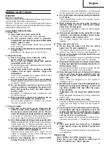
INSTALLING AND REM OVING BITS

WARNING

Be sure to sw itch pow er OFF and disconnect the
plug from  the receptacle to avoid serious trouble.

1. Installing bits
(1) Clean and insert shank of bit into the collet chuck

until shank bottom s, then back it out approxim ately
2 m m .

(2) With the bit inserted and pressing the lock pin

holding the arm ature shaft, use the 23 m m  w rench
to firm ly tighten the collet chunk in a clockw ise
direction (view ed from  under the router). (Fig. 1)

CAUTION

Ensure that the collet chuck is firm ly tightened after
inserting a bit. Failure to do so w ill result in dam age
to the collet chuck.

Ensure that the lock pin is not inserted into the
arm ature shaft after tightening the collet chuck.
Failure to do so w ill result in dam age to the collet
chuck, lock pin and arm ature shaft.

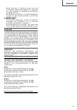
(3) Be sure to use a chuck sleeve w hen using a 6 m m

bit w ith a collet chuck capacity of 8 m m . First insert
the chuck sleeve deeply in the collet chuck, then
insert the bit in the chuck sleeve. Tighten the collet
chuck firm ly as in step (1) and (2).

2. Removing Bits

When rem oving the bits, do so by follow ing the
steps for installing bits in reverse order.

CAUTION

Ensure that the lock pin is not inserted into the
arm ature shaft after tightening the collet chuck.
Failure to do so w ill result in dam age to the collet
chuck, lock pin and arm ature shaft.

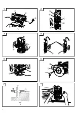
HOW TO USE THE ROUTER

1. Adjusting depth of cut (Fig. 2)
(1) Use stopper pole to adjust depth of cut.

Place the tool on a flat w ood surface.

Turn the stopper block so that section to w hich the
cutting depth setting screw  on a stopper block is
not attached com es to the bottom  of the stopper
pole. Loosen pole lock knob allow ing the stopper
pole to contact w ith stopper block.

Loosen the lock lever and press the tool body until
the bit just touches the flat surface. Tighten the lock
lever at this point. (Fig. 3)

Tighten pole lock knob. Align the depth indicator
w ith the “ 0”  graduation of scale.

Loosen pole lock knob, and raise until indicator
aligns w ith the graduation representing the desired
cutting depth. Tighten pole lock knob.

Loosen the lock lever and press the tool body dow n
until the stopper block to obtain the desired cutting
depth.

(2) As show n in Fig. 4 (a), loosening the tw o nuts on

the threaded colum n and m oving then dow n w ill
allow  you to m ove dow n to the end position of the
bit w hen the lock lever is loosened. This is helpful
w hen m oving the router to align the bit w ith the
cutting position.
As show n in Fig. 4 (b), tighten the upper and low er
nuts to secure the cutting depth.

(3) When you are not using the scale to set the cutting

depth, push up the stopper pole so that it is not
in the w ay.

2. Stopper block (Fig. 5)

The 2 cut-depth setting screw s attached to the
stopper block can be adjusted to sim ultaneously set
3 different cutting depth. Use a w rench to tighten
the nuts so that the cut-depth setting screw s do not
com e loose at this tim e.

3. Guiding the router
WARNING

Be sure to sw itch pow er OFF and disconnect the
plug from  the receptacle to avoid serious trouble.

(1) Tem plate Guide

Use the tem plate guide w hen em ploying a tem plate
for producing a large quantity of identifically shaped
products.
As show n in Fig. 6, secure the tem plate guide to
the base of the router w ith tw o accessory screw s.
At this tim e, ensure that the projection side of the
tem plate guide is facing the bottom  surface of the
base of the router.
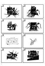
A tem plate is a profiling m old m ade of plyw ood
or thin lum ber.
When m aking a tem plate, pay particular attention
to the m atters described bellow  and illustrated in
Fig. 7.
When using the router along the interior plane of
the tem plate, the dim ensions of the finished product
w ill be less than the dim ensions of the tem plate
by an am ount equal to dim ension “ A” , the difference
betw een the radius of the tem plate guide and the
radius of the bit. The reverse is true w hen using
the router along the exterior of the tem plate.
Secure the tem plate to the w orkpiece. Feed the
router in the m anner that the tem plate guide m oves
along the tem plate as show n in Fig. 8.

(2) Straight guide (Fig. 9)

Use straight guide for cham fering and groove cutting
along the m aterials side.

Insert the guide bar into the hole in the bar holder,
then lightly tighten the 2 w ing bolts (A) on top of
the bar holder.

Insert the guide bar into the hole in the base, then
firm ly tighten the w ing bolt (A).

M ake m inute adjustm ents of the dim ensions betw een
the bit and the guide surface w ith the feed screw ,
then firm ly tighten the 2 w ing bolts (A) on top of
the bar holder and the w ing bolt (B) that secures
the straight guide.

As show n in Fig. 10, securely attach the bottom  of
the base to processed surface of the m aterials. Feed
the router w hile keeping the guide plane on the
surface of the m aterials.

4. Adjusting the rotation speed (M odel M 8V2 only)

The M 8V2 has an electronic control system  that
allow s stepless rpm  changes.
As show n in Fig. 11, dial position “ 1”  is for m inim um
speed, and position “ 6”  for m axim um  speed.

5. Cutting
CAUTION

Wear eye protection w hen operating this tool.

Keep your hands, face and other body parts aw ay
from  the bits and any other rotating parts, w hile
operating the tool.

Summary of Contents for M 8SA2

Page 1: ...Фрезеры Hitachi M8V2 Инструкция пользователя ...

Page 2: ...Handling instructions Bedienungsanleitung à Read through carefully and understand these instructions before use Diese Anleitung vor Benutzung des Werkzeugs sorgfältig durchlesen und verstehen q q rst q s s M 8V2 M 8SA2 M8V2 ...

Page 3: ...1 3 5 2 4 6 8 7 1 A ...

Page 4: ...9 13 10 12 14 15 11 16 2 P ...

Page 5: ...17 3 ...

Page 6: ... knob Deutsch Arretierstift Schraubenschlüssel Lockern Anziehen Anschlagstift Skala Tiefe Indikator Schaftarretierungsknopf Anschlagblock Lösen des Sicherungshebels Mutter Gewindestab Einstellschraube der Frästiefe Schablonenführung Schraube Fräse Schablone Gerade Führung Parallelanschlag Führungsebene Stangenhalter Vortriebschraube Führungsstangen Flügelschraube A Flügelschraube B Einstellscheibe...

Page 7: ...àáàâãèñ âÙÛàñßÛè ÞßàáàâãäÝ îëàÛ ö øùúûüý üþÿþ þ ü çèÝÛè Þßéâ éãï Ú âé ïîàÝ ØéòÙëñßàâ åèîëàãè Üãß Øé éP óèîëàã è èáâè ëñì èñ áëèÚßÜãè îÜÛÚèßàâ îâÙÚè àõà àÝ Üãß íáàâãäÝ îâÙÚ ÞßàáàâãäÝ îàëß Ú èòãÙßä Úßéâ ãé ÞßàáàâãäÝ îàëß Ú èòãÙßä Úßéâ ãé çâèõÙÜâà èããäÝ õÜÚÛ Øè éõÜãÜßï ÞÜÚßé è áÜßèãÜñ æâé éâãàòà ÚßèãÛè ðèòàßà Ûè âè éãÜé âé Pè èëÜÛ ì þ ü ù üþ þ øû þ û ...

Page 8: ...accidents d Remove any adjusting key or wrench before turning the power tool on A wrench or a key left attached to a rotating part of the power tool may result in personal injury e Do not overreach Keep proper footing and balance at all times This enables better control of the power tool in unexpected situations f Dress properly Do not wear loose clothing or jewellery Keep your hair clothing and g...

Page 9: ...firmly during operation 2 The bit is very hot immediately after operation Avoid bare hand contact with the bit for any reason Bottom of Sub base A B C 16 5 mm 18 mm 18 5 mm 20 mm 4 5 mm 25 5 mm 27 mm 28 5 mm 30 mm 20 mm 6 mm 8 m m 2 Chuck Sleeve 8 6 3 Trimmer Guide Fig 14 4 Collet Chuck 8 mm 5 Collet Chuck 1 4 6 Fine adjustment knob Fig 17 Optional accessories are subject to change without notice ...

Page 10: ...Fig 4 b tighten the upper and lower nuts to secure the cutting depth 3 When you are not using the scale to set the cutting depth push up the stopper pole so that it is not in the way 2 Stopper block Fig 5 The 2 cut depth setting screws attached to the stopper block can be adjusted to simultaneously set 3 different cutting depth Use a wrench to tighten the nuts so that the cut depth setting screws ...

Page 11: ...h inspection and replacement on this tool should ONLY be performed by a HITACHI AUTHORIZED SERVICE CENTER 5 Replacing supply cord If the supply cord of Tool is damaged the Tool must be returned to Hitachi Authorized Service Center for the cord to be replaced 6 Service parts list CAUTION Repair modification and inspection of Hitachi Power Tools must be carried out by a Hitachi Authorized Service Ce...

Page 12: ...tzen Sie Ihren Verstand ein wenn Sie mit Elektrowerkzeugen arbeiten Benutzen Sie keine Elektrowerkzeuge wenn Sie müde sind oder unter Einfluss von Drogen Alkohol oder Medikamenten stehen Bei der Arbeit mit Elektrowerkzeugen können bereits kurze Phasen der Unaufmerksamkeit zu schweren Verletzungen führen b Benutzen Sie Schutzausrüstung Tragen Sie immer einen Augenschutz Schutzausrüstung wie Staubma...

Page 13: ...tigt wird VORSICHT Von Kindern und gebrechlichen Personen fernhalten Werkzeuge sollten bei Nichtgebrauch außerhalb der Reichweite von Kindern und gebrechlichen Personen aufbewahrt werden VORSICHTSMASSNAHMEN BEI VERWENDUNG DER OBERFRÄSE 1 Einhändiges Arbeiten ist unstabil und gefährlich Man muß darauf achten daß das Werkzeung mit beiden Händen w ährend des Betriebs gut festgehalten wird 2 Die Fräse...

Page 14: ... der Fräsen Beim Abnehmen von Fräsen die folgenden Schritte in umgekehrter Reihenfolge durchführen VORSICHT Achten Sie darauf dass der Arretierstift nach dem Anziehen des Spannfutters nicht in den Geräteschaft greift Falls doch kommt es zu Beschädigungen des Spannfutters des Arretierstifts und des Geräteschaftes VERWENDUNG DER OBERFRÄSE 1 Einstellen der Schnitttiefe Abb 2 1 Benutzen Sie den Anschl...

Page 15: ...ere Körperteile vom Fräsw erkzeug und säm tlichen anderen bew eglichen Teilen fern w enn Sie m it dem Werkzeug arbeiten 1 Wie in Abb 12 gezeigt die Fräse aus dem Werkstück nehmen und den Umschalthebel in EIN Stellung stellen Nicht den Fräsvorgang beginnen bevor die Fräse volle Drehzahl erreicht hat 2 Die Fräse dreht sich im Uhrzeigersinn in Pfeilrichtung an der Basis Um maximale Fräswirkung zu erz...

Page 16: ...r normalen Verschleiß zurückzuführen sind Im Schadensfall senden Sie das nicht zerlegte Elektrowerkzeug zusammen mit dem GARANTIESCHEIN den Sie am Ende der Bedienungsanleitung finden an ein von Hitachi autorisiertes Servicecenter ANMERKUNG Aufgrund des ständigen Forschungs und Entwicklungsprogramms von HITACHI sind Änderungen der hierin gemachten technischen Angaben nicht ausgeschlossen Informatio...

Page 17: ...r st Ùts Ó Ó s t r ttst r r st Ùts Ù s s st t r Ù Ù tq Ù Ù r Ó Ùt Ô t Ù s s t s rÙ ts tr Ô t Ù r Ù r s Ù r r Ù s r Ó Ô st t rt Ù s t r s s st t Ù s r Ù s r Ùt t q t r r Ù r Ù s q Ù Ô s r st t r Ù Ù tq Ù Ù r r Ù Ù tq t st t s Ô tt Ù Ù q s Ó Ó s r r r Ù r r Ù r s s ttst st t tq s t t s Ô t Ù Ù r s st t Ù r tq Ù Ù s t r Ù r Ù qÙ Ù r Ó Ó r Ù tsÙ q Ô t r r st t t ...

Page 18: ... ßÐ Ï ÓÒßÐ ÑÐ â ÑÕÑ ã ä ÑÐ ÔÓ ß àå Ô ßæ Óå Õ å Ô ß ßÐ ß ÏáÑ ß Ó Òß ß á ß ç è Ü Ü Ü Ü Ý é êëìíîëïðîñí ïòíëðóôíðí õ ö øùúûüýþ ÿ þ ü Ò àÑ ßÐ ßá ßÐ Ñ ßÐ å Ï æß Óå Ö å åß ß å ßß Ô ß Ï Ô ßÐ àÑ ÏÐ å Ñ Ñ å Ù Ý Ú Ý Ð Ö ß Ö ß Ñ Ñ ßÐ ß Ñæ ßÐ ßá ßÐ Ü ôïðëí í í ïîí îí ðó ëó ó ðì ëì ðïë ...

Page 19: ...17 P P P q qrs t P q qrs P q qrs P 20 mm 6 mm 8 m m ...

Page 20: ...18 P q r s t P s P P t t P s ...

Page 21: ...19 P qrs t qrs t P P P ...

Page 22: ...20 P s s qr t t t r t q q t q q q q q q q q r q r r t t q t t r r q q q q t q q r q q t q t q r q t q r t t q q t q t r q q t r t t t q t r r t q r t q r q t q q t ...

Page 23: ...21 P r r r qs s s t s r s q t s q s q s r t s s s r q r r s s r q r ...

Page 24: ...22 P qrsts qrsts 20 mm 6 mm 8 m m ...

Page 25: ...23 P qrst q s r s s ...

Page 26: ...24 P ...

Page 27: ...25 s P P s s r r r r r r r r q r r t t Ü r r t r r q r r r r t r r r r r q s r r r t s t t r r r r r r t t r r t q r s r q r t q r r r t r r r r ...

Page 28: ... r s s t t t t t r s s s ss s s t t t t t tt t t q t t r s s t t t t t tt tt s Ó t q t t t t t t t t q t t q t t t t ÏÐÑ Ü ÒÔ Õ Ö ØÙ ØÙ ÚÛ Ý Þ ßà á â Õ ã ä åæÞ åæ Û Õ Ô â ã Ò æ Õ Ò ã Õ ç èéêëìíî ìïìðñí ò Õ ò ó ô Þæ æ Ðæ æ õ æ å ...

Page 29: ...27 P P P Ü Ü á á á qrst s s qr Ü qr á qrst s s á 20 mm 6 mm 8 m m ...

Page 30: ...28 P P qr st r st s s t P é é é sqr ...

Page 31: ...29 P P ...

Page 32: ...P s qs qs s r P r P P r P ú P s Pqs s s ú tP qs t s tP P r P r tP P r sr Pqs P s s s ú P P qs s P P P tP P ú P P r P P s P P qs s P s P s P r t P st P P ú r s r s s P s P s P s q P q q P r r P s s P P P q r P P P P t P P P r P q r s P P P P P s s r r P s P s P s r P P P P P P r P r P r P s P P P s P ...

Page 33: ...31 P P P ú q rs t q t t r r r r sr qr rs t s r t t ú qr q r t r s r s r rs t P ...

Page 34: ...32 4 Up P P P s q rt t s r r P P t s s s s s r s s s s 20 mm 6 mm 8 m m ...

Page 35: ...33 P P P P P P P P P P P P P P P P P P P P P P qrs t qr s rts P P P P P P P P Ú r P P P P P P P P P P P P P P P P P P P P P P P P P ...

Page 36: ...34 P P q ...

Page 37: ...35 s s s s P s s s s P P P s P s s s s P P s P s s s s s s s s P s s P P P P P s s P P s P s s s P s s s s s P P ...

Page 38: ...Ò Ø Ù ÙÒ ÚÛÚ Ú ØÚ Ú Ü ÝÞßÝàáâáàáã ä Ò æ Ò Ú Ò ÚÛ Ò ÚÜ áàçèé êÝààáëâáìáë ëíç î ïðñïòó ô õ Ò Ú ÙÒ Ø Ù ØÒ Ú ÔÚ Ò ô ôÒ Ò Ú Ú Ò Ú Ò ô Õ Ù Ù Ò Ú Õ Ü ö øïù úïûïøï ïñïüýïþó ÿ æÔ Õ Ù Õ Ù Ù Ò Ú Õ Ü ÿ æÔ Õ Ù Ò ÒÔÚ ÚÛÚ Ú Ò Ô õ ÒÔ ÙÒ æ Û Ø Û Ò ÑÚÙÙÚ Ò Ù ôÒ ÒØÚ Ú Ü ïýøï ï Û ô Ù Ô Õ Ù Ù õ ÒÔÒ Ú Ô Ò ØÒ Ú ÔÚ Ò ô Ñ Ù ØÚ Ò ØÚ Ô Ø Õ Ü Ô Ø Õ Õ ØÚ ÙÚ Ú ÑÒ Ô Ô Ù Ü 6 mm 8 m m ...

Page 39: ...37 s s s s P s q r q t s q s s s s ç s ...

Page 40: ...38 t t t Ó t t t t ß ß t P ß t t t t t ß t t t t ß t Ó t t ß Ó ß Ó t q r s r t Ö r t t t t t ...

Page 41: ...P 39 è è è í í Ô í í í Ô è Ô Ô ù Ô Ô Ô Ô ò Ô í Ô Ô Ô í í Ô í è Ô í è à Ô Ô í q ã r s Ô Ô Ô Ô í í Ô Ô t Ô í í Ô Ô Ô Ô í ù Ô í Ô Ô Ô Ô à Ô ...

Page 42: ... í í í Ô í Ù í í í Ô à í í Ï í Ù à qrst t r t t t ts r t ts r t rst t tr t r t t s t t s str r t str rst t t Öt s t r t r t Ö r Öt t s rst è t r r tr t Ö t s st Ö t ó Ð Ñ Ò ÓÕ Ò ÓÕ Ø Ú Û Ü Ý Þ ß á Ü Û âÚ Ü Ü Ýã Ú Û äå æçÞ Ü æç Ü ...

Page 43: ...P 41 è î ì è Ô Ñ Ñ ñ ñ ñ Ô Ñ Ñ Ñ Ñ à è í í q rs t s ì Ô q í ì Ñ Ñ à í ä è í è í è ä è è è í Ñ Ñ Ñ ì è A B C 16 5 mm 18 mm 18 5 mm 20 mm 4 5 mm 25 5 mm 27 mm 28 5 mm 30 mm 20 mm 6 mm 8 m m ...

Page 44: ...P 42 è à è è Ï è è Ô q r s q tr q r t srt r à è è Ô Ô à è è ò è è à è ...

Page 45: ...P 43 Ñ è Ñ q r st ù st î Ñ î t st t à Ï Ï Ï Ï Ï Ï Ï Ï ...

Page 46: ...39 HANDLE L A 1 40 SPRING GUIDE 2 41 PLUNGER SPRING R 1 42 PLUNGER SPRING L 1 43 MACHINE SCREW W WASHERS M4 12 1 44 LEVER C 1 45 LOCK SCREW M6 1 46 END BRACKET 1 Item Part Name Q TY No 47 LOCK PIECE 1 48 LOCK SCREW M10 1 49 LEVER A W O STOPPER 1 50 MACHINE SCREW W WASHERS M6 10 1 51 HANDLE R A 1 52 HANDLE R B 1 53 TAPPING SCREW D5 50 4 54 CORD A 1 55 BALL BEARING 6004TIXVV 1 56 THRUST NUT 1 57 BEA...

Page 47: ...A 1 39 SPRING GUIDE 2 40 PLUNGER SPRING R 1 41 PLUNGER SPRING L 1 42 MACHINE SCREW W WASHERS M4 12 1 43 LEVER C 1 44 LOCK SCREW M6 1 45 END BRACKET 1 46 LOCK PIECE 1 Item Part Name Q TY No 47 LOCK SCREW M10 1 48 LEVER A W O STOPPER 1 49 MACHINE SCREW W WASHERS M6 10 1 50 HANDLE R A 1 51 DIAL COVER 1 52 HANDLE R B 1 53 TAPPING SCREW D5 50 4 54 BALL BEARING 6004TIXVV 1 55 THRUST NUT 1 56 BEARING COV...

Page 48: ... stamp dealer name and address P Deutsch é GARANTIESCHEIN Modell Nr Serien Nr Kaufdaturn Name und Anschrift des Kunden Name und Anschrift des Händlers Bitte mit Namen und Anschrift des Handlers abstempeln é qr st t t t t r t t é ÏÐÑÒÐ ÓÔÕÔ Ö ØÖ Ï ÙÔÚÛÔÑÏ Ï Ô Ü ÚÔ ÔÚÝÏ Ô ÙÔÚÛÔÑÏ Ï Ô Ü Ï Ô Þß àÔ ØÐÜÕÔá ÛÑ ÜÏÕ ÑÔÚÛÔÑÏ Ï Ô Ü Ï Ôâ ...

Page 49: ...47 ...

Page 50: ... have reached the end of their life must be collected separately and returned to an environm entally com patible recycling facility Deutsch Nur für EU Länder Werfen Sie Elektrow erkzeuge nicht in den Hausmüll Gemäss Europäischer Richtlinie 2002 96 EG über Elektro und Elektronik Altgeräte und Umsetzung in nationales Recht m üssen verbrauchte Elektrowerkzeuge getrennt gesammelt und einer umweltgerec...

Page 51: ...nts EN60745 EN55014 and EN61000 3 in accordance with Council Directives 73 23 EEC 89 336 EEC and 98 37 EC This declaration is applicable to the product affixed CE marking Deutsch ERKLÄRUNG ZUR KONFORMITÄT MIT CE REGELN Wir erklären mit alleiniger Verantwortung daß dieses Produkt den Standards oder standardisierten Dokumenten EN60745 EN55014 und EN61000 3 in Übereinstimmung mit den Direktiven des E...

Page 52: ...редства защиты головы Лобзики электрические Вышки и рабочие площадки Фрезы Наборы ручных инструментов Рубанки электрические Средства защиты органов слуха Средства защиты органов дыхания Средства защиты глаз и лица Тиски и струбцины ...

Reviews: