background image

Microlok II

® 

Serial-to-Ethernet Converter (SEC) 

Copyright 2019                           SM6800O Rev. 1, March 2019 


3-11 

From the SEC configuration page you can view current network settings and access links to 

functions for reconfiguring the unit. Use the following procedure to access the SEC 

configuration page. 

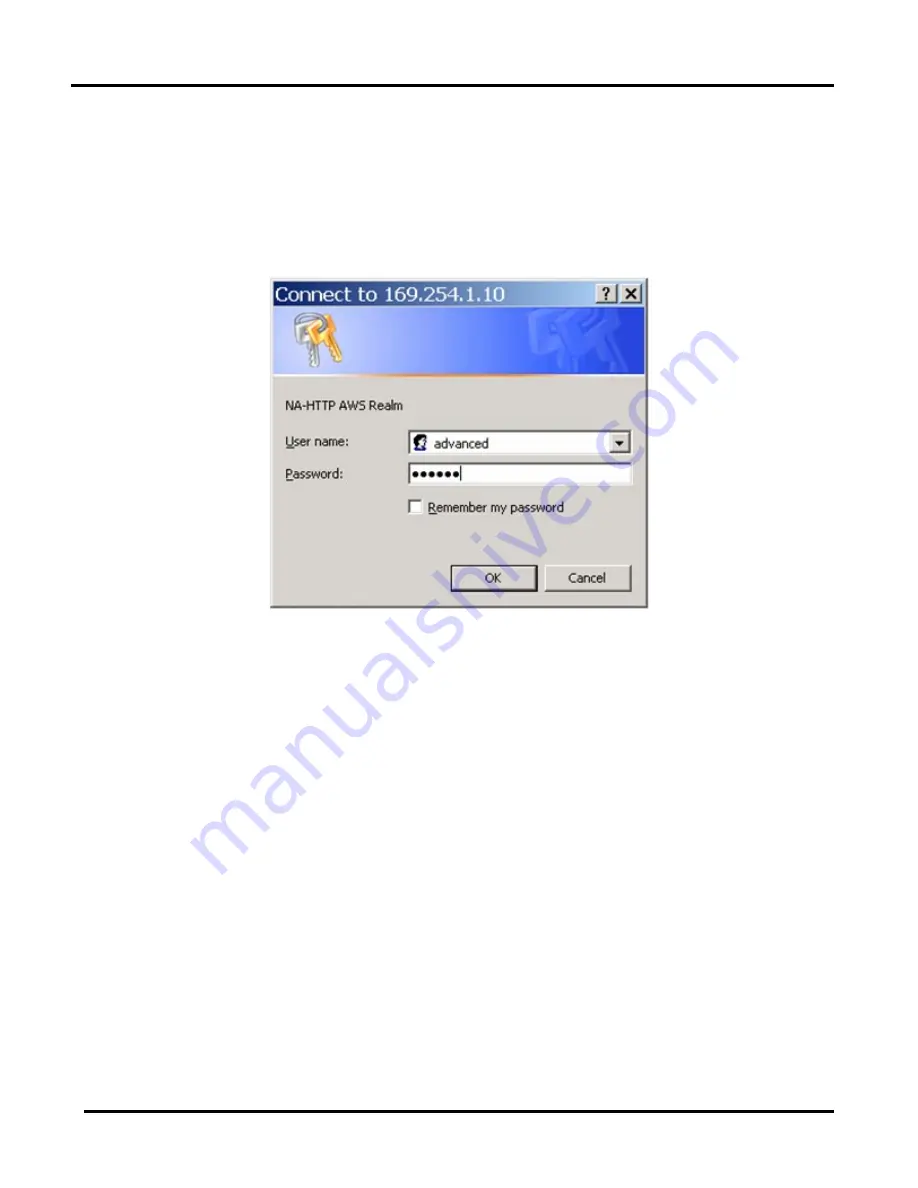
1.  Using Internet Explorer, type the IP address, 169.254.1.10, into the address box of the 

browser and press the Enter key on your keyboard.  Before granting you access to the 

configuration home page, the system will prompt you for a user name and password 

(

X

Figure 3-11

X

)


Figure 3-11  -  SEC Login Dialog 


Summary of Contents for Microlok II

Page 1: ...SM 6800O 1000 Technology Drive Pittsburgh PA 15219 645 Russell Street Batesburg SC 29006 Microlok II Serial to Ethernet Converter SEC STS Part No N16920401 Installation Operation Troubleshooting ...

Page 2: ......

Page 3: ...the prior written consent of STS Important Notice STS constantly strives to improve our products and keep our customers apprised of changes in technology Following the recommendations contained in the attached service manual will provide our customers with optimum operational reliability The data contained herein purports solely to describe the product and does not create any warranties Within the...

Page 4: ...rolok II Serial to Ethernet Converter SEC Copyright 2019 SM6800O Rev 1 March 2019 ii Revision History Rev Date Nature of Revision Original January 2008 Initial Issue 1 March 2019 Hitachi Rail STS Branding ...

Page 5: ...e SEC Configuration Screens 3 4 3 5 1 22BChecking Internet Explorer 3 4 3 5 2 Deleting Saved Temporary Internet Files 3 8 3 6 15BConnecting a New SEC to a PC for Configuration 3 10 3 7 16BAccessing the SEC Configuration Page 3 10 3 8 17BConfiguring the SEC 3 12 3 9 18BSEC Configuration Options 3 17 3 9 1 24BChanging Network Settings 3 17 3 1019BUploading new SEC Firmware 3 17 3 1120BIdentifying IP...

Page 6: ... March 2019 vi 5 2 5 Gateway 5 4 5 2 6 Broadcast 5 4 5 2 7 Learn 5 4 5 2 8 Port 5 5 5 2 9 Pair 5 5 5 3 Static Routing Table 5 5 5 3 1 UDP Section Options 5 5 5 3 2 TCP Section Options 5 6 5 4 HMAC Section Options 5 7 6 5BParts List 6 1 7 6BRAIL Team and Technical Support 7 1 ...

Page 7: ...irmation Dialog Box 3 9 Figure 3 10 Low or No Connectivity Mode Balloon Message 3 10 Figure 3 11 SEC Login Dialog 3 11 Figure 3 12 SEC Configuration Home Page 3 12 Figure 3 13 SEC Advanced Tools Page 3 13 Figure 3 14 SEC Flash0 Directory Page 3 14 Figure 3 15 File Upload Page 3 15 Figure 3 16 FLASH0 Directory Page 3 15 Figure 3 17 Back Button in Web Browser on FLASH0 Directory Page 3 16 Figure 3 1...

Page 8: ...opyright 2019 SM6800O Rev 1 March 2019 viii List of Tables Table 1 1 Operating Specifications 1 2 Table 1 2 Mechanical Specifications 1 2 Table 3 1 SEC to Microlok II Connections 3 2 Table 5 1 Factory Configuration File 5 1 Table 6 1 Parts List 6 1 ...

Page 9: ...ns present considerations which if ignored could result in damage to the equipment Warnings present considerations which if ignored could result in personnel injury or even death Electrical equipment can have high voltage and high temperature areas Caution should be exercised when working around electrical equipment Care must be taken to follow all local and railroad safety requirements 1 2 8B Abb...

Page 10: ...tagram Protocol STS Union Switch Signal VDC volts direct current 1 3 9BSpecifications The Microlok II SEC meets all applicable environmental EMI and vibration tolerance specifications The operating specifications for the N16920401 SEC are shown in XTable 1 1X Table 1 1 Operating Specifications Parameter Value System Power Source Voltages 9 8 to 16 2VDC Temperature Range 40 C to 70 C Humidity 0 to ...

Page 11: ...19 1 3 Height 6 77 in 17 2 cm Width 4 41 in 11 2 cm not including the DIN rail Mounting Tabs Depth 1 38 in 3 5 cm Weight 0 74 lb 337g for the wholly assembled unit Mounting Standard DIN Rail Mount 6 77 REF 17 2 cm 4 4 1 REF 1 38 11 2 cm 3 5 cm Figure 1 1 Overall Dimensions of the SEC ...

Page 12: ...Microlok II Serial to Ethernet Converter SEC Copyright 2019 SM6800O Rev 1 March 2019 1 4 ...

Page 13: ...urce to provide isolated power An internal web server interface that provides screens for configuring the SEC unit The SEC has a built in web interface Using this interface you can inspect each unit s operational status and product information You can also configure the unit through the web interface and even upgrade its firmware in the field Access to the user interface is password protected See ...

Page 14: ...Microlok II Serial to Ethernet Converter SEC Copyright 2019 SM6800O Rev 1 March 2019 2 2 Figure 2 1 SEC Front Panel ...

Page 15: ... A serial cable A standard Ethernet cable for connecting the SEC to an Ethernet network A crossover Ethernet cable for connecting the SEC to a PC A WAGO power connector STS supplied 3 1 10BPower Source Cable Configuration Power is supplied through the front mounted WAGO cage clamp style connector It is recommended that 14 18AWG wire be used for the power connections The negative battery is connect...

Page 16: ...TOR 5 SIG COMM 4 3 TXD 2 RXD 1 9 8 7 6 Figure 3 2 DB 9 Connector on the SEC Table 3 1 SEC to Microlok II Connections SEC DB 9 Microlok II Connection Pin No Signal Refer to the Microlok II Service Manual SM 6800B Section 3 5 for connection to the Microlok II System For Port 3 Jumper Pin C14 RTS Output to Pin E10 DCD Input and Jumper Pin E18 RXREF to C18 Signal Common For Port 4 Jumper Pin A14 RTS O...

Page 17: ...SEC Connect the power source by inserting the power leads into the WAGO connector XFigure 3 1X 3 Connect the serial cable to the Microlok II unit and then to the SEC XFigure 3 3X 4 Apply power to the SEC by placing the On Off rocker switch on the front of the SEC in the ON position 5 Insert one end of an Ethernet crossover cable to the Ethernet connector of the SEC and the other end to the Network...

Page 18: ...ration functions of the SEC you may need to do one or both of the following Specify the IP address range used by the SEC in Internet Explorer s Settings Delete the Temporary Internet Files saved by Internet Explorer This section describes each of these procedures 3 5 1 22BChecking Internet Explorer You may need to configure your Internet Explorer settings to allow the browser to access the IP addr...

Page 19: ...ight 2019 SM6800O Rev 1 March 2019 3 5 Figure 3 4 Accessing the Internet Options on Internet Explorer Version 6 2 In the Internet Options pop up box click on the Connections tab See XFigure 3 5X 3 In the Connections tab click on the LAN Settings button ...

Page 20: ...Microlok II Serial to Ethernet Converter SEC Copyright 2019 SM6800O Rev 1 March 2019 3 6 Figure 3 5 Connections Tab on the Internet Options Box ...

Page 21: ...e LAN Settings pop up box will open XFigure 3 6X If the Use a proxy server for your LAN is unchecked leave it unchecked and skip Steps 5 and 6 If the box is checked proceed with Steps 5 and 6 5 Click on the Advanced button to open the Proxy Settings pop up box Figure 3 6 LAN Settings Pop Up Box ...

Page 22: ... 3 5 2 Deleting Saved Temporary Internet Files To ensure the PC is working with the latest version of software it is necessary to delete any files which Internet Explorer IE may have saved from earlier installations Delete these saved files using the following procedure These temporary files can be deleted without causing any problems 1 Start Internet Explorer 2 Select Tools Internet Options XFigu...

Page 23: ...ck on Delete Files button in the Temporary Internet files area In response the system will display a confirmation box asking if you want to delete the temporary Internet files XFigure 3 9X Figure 3 9 Delete Files Confirmation Dialog Box 5 Click OK The PC will then delete the temporary Internet files 6 Click OK to close the Internet Options dialog box ...

Page 24: ...To use the Ethernet port in a network you must set the IP address to a unique value using the following procedure 1 Connect the PC to the SEC either directly with an Ethernet crossover cable or through an Ethernet hub or switch using a standard Ethernet cable 2 To configure the PC to communicate with the SEC wait for the PC to go check its local area connections A message will appear XFigure 3 10X...

Page 25: ...ons for reconfiguring the unit Use the following procedure to access the SEC configuration page 1 Using Internet Explorer type the IP address 169 254 1 10 into the address box of the browser and press the Enter key on your keyboard Before granting you access to the configuration home page the system will prompt you for a user name and password XFigure 3 11X Figure 3 11 SEC Login Dialog ...

Page 26: ...s also displayed Currently only Peer Routing Mode is supported For information on configuring the SEC using the Advanced Tools page see Section X3 8X 3 8 17BConfiguring the SEC All of the SEC configuration settings are maintained in the niacfg ini file that resides in memory in the SEC Configuring the SEC involves making changes to the niacfg ini file The following procedure takes you through the ...

Page 27: ...net Explorer s saved temporary Internet files See Section X3 5 2X for the procedure 1 Access the SEC configuration page See Section X3 7X for the procedure 2 On the SEC configuration page click on the Network Adapter Advanced Options link XFigure 3 12X The system displays the Advanced Tools page XFigure 3 13X Figure 3 13 SEC Advanced Tools Page ...

Page 28: ...in this file The configuration options are described in Section X3 9X 6 When you have finished editing the niacfg ini file save it to a specific location on the PC such as the Desktop and note the location You will need to find this file again in the Upload process At this point you can close the text editor This will return you to the SEC Flash0 directory page Figure 3 14 7 Upload the revised nia...

Page 29: ...File Upload Page d While the file is uploading the screen won t change When it is finished the system displays the FLASH0 file list as shown in XFigure 3 16X Figure 3 16 FLASH0 Directory Page 8 Return to the Advanced Tools page by clicking on the Back button on your web browser as shown in XFigure 3 17X ...

Page 30: ... the SEC which stores the configuration files and includes the Ethernet connection the Digi EPROM chip and two LED indicators as shown in XFigure 3 19X Figure 3 18 Advanced Tools Page 10 The green LED on the Ethernet connection on the front of the SEC will come on while it is booting When it has booted up the green LED will go out and the yellow Ethernet LED will turn off for a brief moment A few ...

Page 31: ...me section as the IP address To access these settings see Section X3 8X for the procedure NOTE Changes to the configuration file should be made only with information supplied by the networking or IT personnel GENERAL IP 192 168 1 10 NETMASK 255 255 0 0 GATEWAY 192 168 1 1 DHCP is not supported Figure 3 20 GENERAL Section of the niacfg ini File 3 10 19BUploading new SEC Firmware The design of the S...

Page 32: ...selecting Start All Programs Accessories Command Line Shell The system displays the command line shell as shown in XFigure 3 21 Figure 3 21 Command Line Shell Window 3 Using the cd command change the directory to the one where you downloaded the firmware in Step 1 If you saved your new firmware file to the root directory type the following on the command line and press the Enter key cd C 4 Establi...

Page 33: ...ftp connection by typing quit and pressing the Enter key as follows ftp quit 10 The SEC unit will program itself and reboot in approximately 10 seconds The green LED on the Digi module Ethernet Connector XFigure 3 19X will come on while it is booting When it has booted up the green LED will go out and the yellow Ethernet LED will turn off for a brief moment A few seconds after the yellow LED comes...

Page 34: ...l down menu 3 From the Select Your Product for Support pull down menu choose Digi Connect ME and click SUBMIT The system displays the Digi Connect ME support page part of which is shown in XFigure 3 22X Figure 3 22 Digi Connect ME Tech Support Information Page 4 Click on the Diagnostics Utilities and MIBs link A list of available utilities and a combo box for selecting OS specific utilities displa...

Page 35: ...to the location of the file and double click on it After downloading the utility is ready to use 3 12 21BErasing the Existing Configuration File If the file system on the SEC is not working you may wish to completely erase the configuration file niacfg ini from the embedded file system using the following procedure 1 Make sure you have a known good or factory default settings configuration file on...

Page 36: ...ter Advanced Options link XFigure 3 12X 4 On the Advanced Tools page click on the Erase link XFigure 3 13X The system displays a password box XFigure 3 24X Figure 3 24 Erases Flash Function Password Dialog Box 5 Type in erase for both the user name and password and click OK The system will display the confirmation screen shown in XFigure 3 25X Figure 3 25 Erase Flash Function Confirmation Page ...

Page 37: ...If that works upload a new configuration file See Section X3 8X If deleting the configuration file does not correct the problem click the Erase Flash button The system will delete the configuration file if it is not already deleted and then reboot the SEC thereby erasing the settings in Flash memory After the SEC reboots you can upload a new configuration file ...

Page 38: ......

Page 39: ...ngs configuration file See Section X3 12X Confirm that there is not another unconfigured SEC unit on the same switch or hub and that there is no other device with the same IP address Confirm that the SEC is turned on the power source is operating normally and that power is being delivered to the connection point Check the power cable connections and reseat the connectors if necessary Check the ser...

Page 40: ...Microlok II Serial to Ethernet Converter SEC Copyright 2019 SM6800O Rev 1 March 2019 4 2 ...

Page 41: ...type Comments begin with a and continue to the end of the line The order of the options doesn t matter but each option has to be within its correct section For example BIT_RATE can t be in the UDP section it must be in the GENERAL section NOTE The factory niacfg ini file is provided on the CD which was shipped with the SEC Table 5 1 Factory Configuration File This is the niacfg ini configuration f...

Page 42: ...e 192 168 1 2 60000 002B 0022 34AAAA78 43AAAA78 if PAIR 1 then the pair must be present Example 192 168 1 16 60000 00CA 0065 PAIR 1 format MII_PEER1 Port 1 Destination IP address 192 168 1 16 which hosts MLK Address 202 192 168 1 10 60000 00CA TCP This section is similar to UDP The difference is each connection has its own host port number The format of entries in this section are as follows host ...

Page 43: ...d The value of this parameter is of no meaning to the SEC 5 2 1 Mode This parameter is listed as MODE 1 in the factory file The only available option is 1 for Peer Routing mode If this parameter is set to anything but 1 the SEC will not route Peer messages 5 2 2 Bit Rate This parameter is listed as BIT_RATE 38400 in the factory file It sets the bit rate that the SEC uses to communicate with the Mi...

Page 44: ...nternal tables If the address is found in the tables the message is directed to the appropriate Microlok II unit independent of the Broadcast setting However if the Broadcast parameter is set to 0 and the destination address is not found the message will discarded If the Broadcast is set to 1 and the destination address is not found then the message will be broadcast across the entire local subnet...

Page 45: ...ce address In this case the only way to uniquely identify where each message should go is to use both the source and destination addresses as a pair In the absence of a value for this parameter in the configuration file Pair will default to a value of 0 5 3 Static Routing Table Note The UDP and TCP sections are where the static routing table is defined Note Static tables can contain entries for it...

Page 46: ... 20 Messages sent from the station have a source address of 10 and a destination address of 20 PROTOCOL MII PEER ADJUSTABLE PORT 4 ADJUSTABLE MII ADDRESS 20 STATION NAME STATION_2 ADJUSTABLE PEER ADDRESS 10 This definition is the other end of the communication Messages sent from this link have a source address of 20 and a destination address of 10 With PAIR routing the following definition would w...

Page 47: ... 20 MICROLOK II B STATION_2 MII ADDRESS 20 PEER ADDRESS 10 SEC A SEC B 192 168 1 16 IP ADDRESS 192 168 1 17 IP ADDRESS SEC A connects to SEC B at 192 168 1 17 on port 4001 SEC B accepts a connection on port 4001 from SEC A at 192 168 1 16 4001 192 168 1 16 4001 000A 6001 192 168 1 17 4001 0014 mlk_ addr_list target_ip_addr target_port local_port TCP IP NETWORK Figure 5 1 An Example of a the Format...

Page 48: ...Server IP address The Key Server distributes keys PORT 5840 HMAC Key Server IP port Note This must be the port number that the key server is running on KEY TIMEOUT 2000 Time in milliseconds between HMAC Key heartbeat messages The range of this parameter is from 500 to 60000 KEY RETRYS 3 Number of missed heartbeats before any key is declared invalid The range on this parameter is from 0 to 20 ...

Page 49: ...ts List For all but the parts shown in XTable 6 1X there are no user replaceable components in the SEC XTable 6 1X lists the part number of the SEC and its replaceable components Table 6 1 Parts List Item Part Number SEC N16920401 Power Connector 4 pin WAGO connector J7091461910 Fuse 5 amp J071185 ...

Page 50: ...Microlok II Serial to Ethernet Converter SEC Copyright 2019 SM6800O Rev 1 March 2019 6 2 ...

Page 51: ... Technical Support The Rapid Action Information Link Team RAIL Team is a group of experienced product and application engineers ready to assist you to resolve any technical issues concerning this product Contact the RAIL Team in the United States at 1 800 652 7276 or by e mail at Hrailteam hitachirail comH ...

Page 52: ...Microlok II Serial to Ethernet Converter SEC Copyright 2019 SM6800O Rev 1 March 2019 7 2 ...

Reviews: