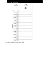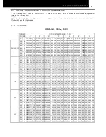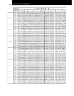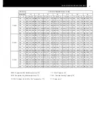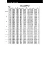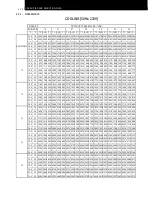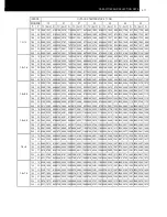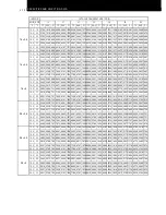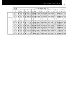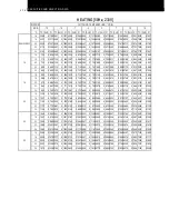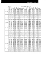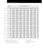
CAPACITIES AND SELECTION DATA
3-2
3.1. SYSTEM SELECTION PROCEDURE
The following system procedure is giving a sample regarding unit selection system, indicating how to use all
parameters showed in this chapter.
3.1.1. SELECTION UNIT FEATURES
Considering the building distribution, the possible indoor
unit position and the available air flow distribution, select
the unit features that are giving the best efficiency and
comfort to each room.
Decide the Outdoor Unit position getting easy service
maintenance and easy refrigerant pipe installation.
Therefore, the maximum indoor unit capacity combined
with outdoor unit should be carefully considered for correct
indoor unit distribution at each building
3.1.2. SELECTION GUIDE
The following guide giving the method for indoor and
outdoor unit selection.
∗
Step 1: Determine the system requirements
Calculate the cooling capacity and heating capacity of
each indoor unit according to the following conditions:
Total Load for each room
Room
Item
1
2
3
1+2+3
Estimated
Cooling Load
kW
2.75
4.24
5.35
12.34
Estimated
Heating Load
kW
2.90
4.60
6.00
13.50
*Example
Temperature Condition
Cooling
Heating
Outdoor Air Inlet
•
Dry Bulb: 35.0ºC
Outdoor Air Inlet
•
Dry Bulb: 7ºC
•
Wet Bulb: 0ºC
Indoor Air Inlet
•
Dry Bulb: 27,0ºC
•
Wet Bulb: 19.0ºC
Indoor Air Inlet
•
Dry Bulb: 20ºC
*Example
∗
Step 2
:
Select Unit Capacity Performance
The unit kW is selected following the Cooling
capacity and Heating capacity showed in the
combination table.
∗
Step 3
:
Read Selected Capacity Performance
The unit performance should be calculated
considering the following correction factors:
1. Cooling and Heating piping length
2. Outdoor unit performance capacity
3. Indoor unit performance capacity for each room
cooling load
Kindly refer to the unit selection combination table for
correct capacity performance.
Summary of Contents for MULTIZONE RAM-40NE2F
Page 11: ...DIMENSIONAL DATA 2 3 2 2 MULTIZONE OUTDOOR UNITS 2 2 1 2 ROOMS MULTIZONE RAM 40NE2F ...
Page 12: ...DIMENSIONAL DATA 2 4 2 2 2 2 ROOMS MULTIZONE RAM 53NE2F Unit mm ...
Page 13: ...DIMENSIONAL DATA 2 5 2 2 3 3 ROOMS MULTIZONE RAM 53NE3F Unit mm ...
Page 63: ...WIRING DIAGRAM 7 2 7 1 MULTIZONE 7 1 1 RAK 15QEF RAK 18REF RAK 25REF RAK 35REF RAK 50REF ...
Page 64: ...WIRING DIAGRAM 7 3 7 1 2 RAM 40NE2F RAM 53NE2F ...
Page 65: ...WIRING DIAGRAM 7 4 7 1 3 RAM 53NE3F ...
Page 68: ...REFRIGERANT CYCLE CYC8 3L 8 1 2 WALL TYPE RAK 50REF ...
Page 69: ...REFRIGERANT CYCLE 8 4 8 2 MULTIZONE OUTDOOR UNITS 8 2 1 2 ROOMS MULTIZONE RAM 40NE2F ...
Page 70: ...REFRIGERANT CYCLE CYC8 5L 8 2 3 2 ROOMS MULTIZONE RAM 53NE2F φ12 7 ...
Page 71: ...REFRIGERANT CYCLE 8 6 8 2 4 3 ROOMS MULTIZONE RAM 53NE3F ...
Page 74: ...CONTROL AND FUNCTION 9 3 9 2 SHIFT VALUE ...
Page 75: ...9 4 CONTROL AND FUNCTION 9 3 DISPLAY OPERATION MODE SETTING ...
Page 76: ...CONTROL AND FUNCTION 9 5 9 4 HOW TO CHANGE THE INTERMITTENT FAN CONTROL SETTING ...
Page 77: ...9 6 CONTROL AND FUNCTION 9 5 HOW TO CHANGE THE FAN SPEED IN COOLING MODE DURING THERMO OFF ...
Page 78: ...CONTROL AND FUNCTION 9 7 9 6 SETTING THE PREVENTION OF MUTUAL INTERFERENCE ...


