Error! Reference source not found.
10-16
CAUTION:
–
DO NOT set various main adaptors in the same
refrigerant cycle.
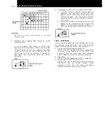
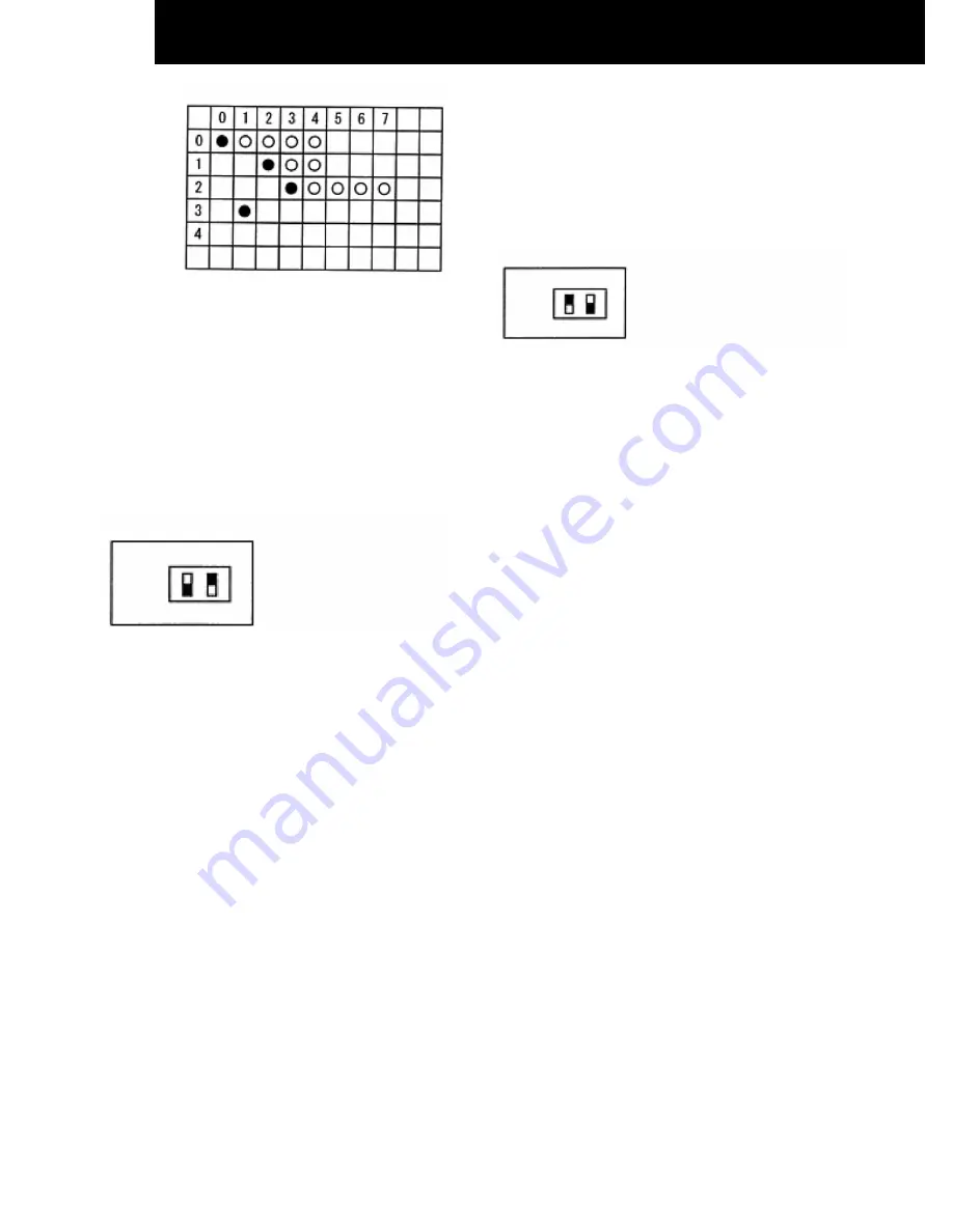
6) Procedure when applying 200V voltage to H-LINK
wiring incorrectly.
In case of applying 200V voltage to H-LINK wiring
incorrectly, the fuse installed in a transmission circuit on
PCB will blow out. In this case, reconnect the wiring
correctly and turn ON No. 2 pin of DSW4 on PCB. The
transmission circuit can be recovered. (If applying this
error again, the transmission circuit can not be
recovered)
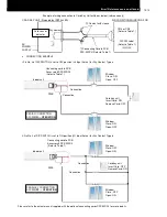
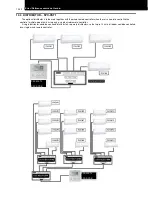
7) Terminating resistance is set in whole H-LINK system.
a) If H-LINK connecting devices like package air-
conditioner are connected besides the RAC
Adaptor, set the terminating resistance by those
connecting devices. The terminating resistance
should be set ON in only one position in whole H-
LINK system.
b) In case that H-LINK is connected only by the RAC
adaptor, set the terminating resistance by the RAC
adaptor. The terminating resistance should be set
ON in only one position in whole H-LINK system.
10.2.5 TEST RUN
Test run should be performed in the following after finishing
the installation, wiring and setting. Refer to the installation
manuals enclosed with the control system equipment.
1) Confirmation of RAC Adaptor Connection
Confirm if the RAC adaptor connection is recognized in
the control system equipments. In case that it is not
confirmed, check the transmission cable, refrigerant
cycle #, indoor unit #, terminal resistance setting etc.
2) Registration
Confirm if the RAC adaptor connection is recognized.
3) Confirmation of RUN/STOP Operation.
Confirm if the room air-conditioner operate correctly by
RUN/STOP
from
the
central
control
system
equipments. Check also if the room air-conditioner
operation changes correctly by each setting.
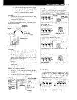
Refrigerant
Unit#
Indoor Unit#
DSW4
Turn ON No.2 pin of
DSW4
ON
1
2
PCB
DSW4
Turn ON No.1 pin of
DSW4
ON
1
2
PCB
Summary of Contents for MULTIZONE RAM-40NE2F
Page 11: ...DIMENSIONAL DATA 2 3 2 2 MULTIZONE OUTDOOR UNITS 2 2 1 2 ROOMS MULTIZONE RAM 40NE2F ...
Page 12: ...DIMENSIONAL DATA 2 4 2 2 2 2 ROOMS MULTIZONE RAM 53NE2F Unit mm ...
Page 13: ...DIMENSIONAL DATA 2 5 2 2 3 3 ROOMS MULTIZONE RAM 53NE3F Unit mm ...
Page 63: ...WIRING DIAGRAM 7 2 7 1 MULTIZONE 7 1 1 RAK 15QEF RAK 18REF RAK 25REF RAK 35REF RAK 50REF ...
Page 64: ...WIRING DIAGRAM 7 3 7 1 2 RAM 40NE2F RAM 53NE2F ...
Page 65: ...WIRING DIAGRAM 7 4 7 1 3 RAM 53NE3F ...
Page 68: ...REFRIGERANT CYCLE CYC8 3L 8 1 2 WALL TYPE RAK 50REF ...
Page 69: ...REFRIGERANT CYCLE 8 4 8 2 MULTIZONE OUTDOOR UNITS 8 2 1 2 ROOMS MULTIZONE RAM 40NE2F ...
Page 70: ...REFRIGERANT CYCLE CYC8 5L 8 2 3 2 ROOMS MULTIZONE RAM 53NE2F φ12 7 ...
Page 71: ...REFRIGERANT CYCLE 8 6 8 2 4 3 ROOMS MULTIZONE RAM 53NE3F ...
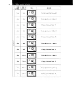
Page 74: ...CONTROL AND FUNCTION 9 3 9 2 SHIFT VALUE ...
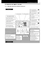
Page 75: ...9 4 CONTROL AND FUNCTION 9 3 DISPLAY OPERATION MODE SETTING ...
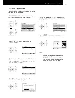
Page 76: ...CONTROL AND FUNCTION 9 5 9 4 HOW TO CHANGE THE INTERMITTENT FAN CONTROL SETTING ...
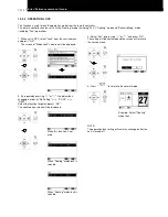
Page 77: ...9 6 CONTROL AND FUNCTION 9 5 HOW TO CHANGE THE FAN SPEED IN COOLING MODE DURING THERMO OFF ...
Page 78: ...CONTROL AND FUNCTION 9 7 9 6 SETTING THE PREVENTION OF MUTUAL INTERFERENCE ...


