


Chapter 13 Option
13 - 55
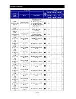
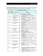
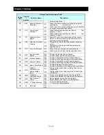
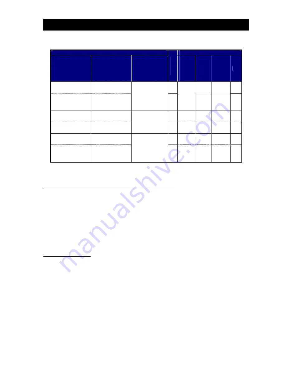
“H” Function
Run
Mod
e
Edit
Defaults
Func.
Code
(WOP)
Name
Description
Initial data
standard
200/400
Initial data
CHN
200/400
Initial data
EU
200/400
Units
H003
(Motor capacity)
Motor capacity
Twelve selections:
0.10/0.20/0.40/0.5
5/0.75/1.10/1.50/2
.20/3.00/3.70/4.00
/5.50
Specifie
d by the
capacity
of each
inverter
model
←
←
kW
H203
(Motor
capacity-M2)
Motor capacity,
2
nd
motor
←
←
kW
H004
(Motor poles)
Motor poles setting
Five selections:
2 / 4 / 6 / 8
4
←
←
pole
s
H204
(Motor poles-M2)
Motor poles setting,
2
nd
motor
4
←
←
pole
s
H006
(M.stabil.const)
Motor stabilization
constant
Motor constant
(factory set),
range is 0 to 255
100.
←
←
H206
(M.stabil.
const-M2)
Motor stabilization
constant, 2
nd
motor
100.
←
←
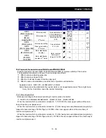
13.2 Top cover for exclusive use of NE-S1series
:
NES1-FFM-M
・
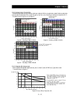
Prepared exclusive top cover NES1-FFM-M (Afterward FFM) to improve usability of the inverter.
The applicable models are as follows. There are respective effects.
①
Effect to improve derating properties
②
Effect to improve Capacitor life
③
Effect not to let dust invade it from the upper part
④
Effect to reduce an installation area at the time of plural mount installation
Applicable model
:
NES1-015
~
022SB/LB,007
~
040HB
Note) Please do not be attached to the inverter which is not an applicable model. There might be an
injury, the fire. In addition, cause the inverter discarding.
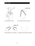
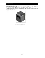
13.2.1 Mounting method
・
Because mounting method varies according to inverter, please be careful.
①
NES1-015
~
022SB/LB,022HB,040HB
②
NES1-015HB
③
NES1-007HB
When the inverter which I purchased is included in
①
, fit FFM in the cover upper surface of the main
body of inverter, and, please use it.
When the inverter which I purchased is included in
②
, After having removed (shaded area) surgically in
nippers for back side tang of FFM of figure 2, fit FFM in the cover upper surface of the main body of
inverter, and, please use it.
When the inverter which I purchased is included in
③
, After having removed (shaded area) surgically in
nippers for back side tang of FFM of figure 2 and 3, fit FFM in the cover upper surface of the main body of
inverter, and, please use it.
Summary of Contents for NES1-002LB
Page 9: ......
Page 21: ......
Page 25: ......
Page 28: ...Chapter 3 Exterior Views 3 3 ...
Page 30: ......
Page 35: ......
Page 53: ......
Page 75: ......
Page 154: ......
Page 196: ......
Page 203: ...Chapter 10 Troubleshooting This chapter describes the troubleshooting methods ...
Page 204: ......
Page 211: ......
Page 219: ......
Page 229: ......
Page 289: ...Appendix Appendix A Appendix A 1 ...
Page 290: ......
Page 292: ...Appendix Appendix 2 ...


